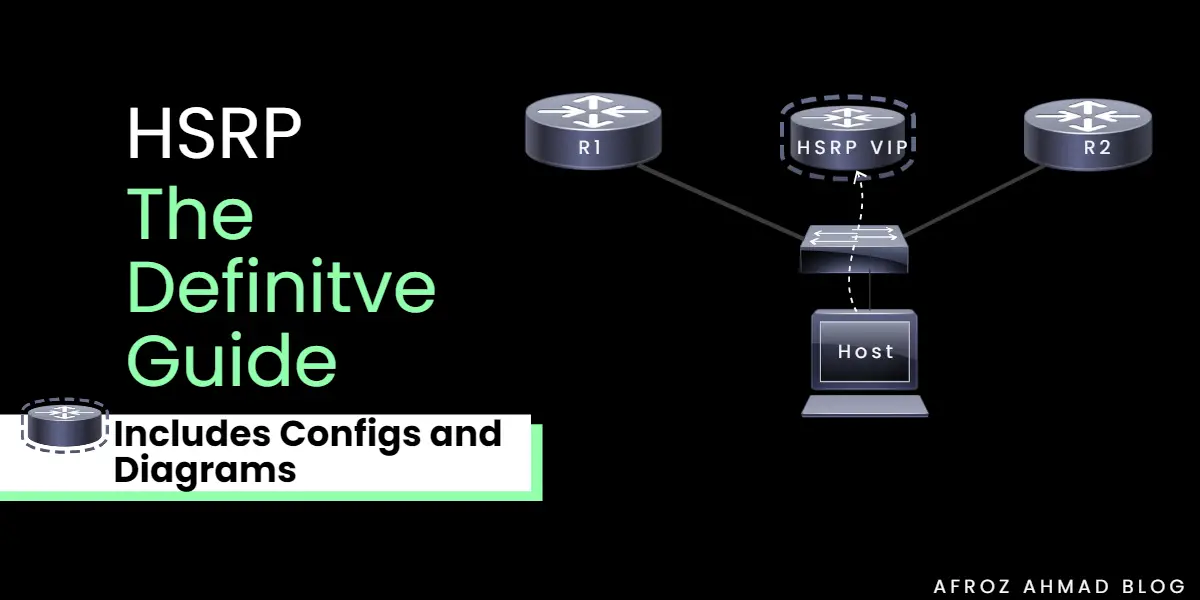
HSRP is an FHRP (First Hop Redundancy Protocol) developed by Cisco to provide redundancy and high network availability almost anywhere in the network where we have two layer3 devices. HSRP config gives a group of routers a virtual IP address and a virtual MAC address to look like one router. If one router doesn’t work, the other router can be the default gateway. The virtual router does not exist; it is merely a target for routers to provide backup to one another. One router is designated as the active router, while the other is marked as the standby router, which takes over management of the group’s virtual MAC address and IP address if the active router fails.
HSRP protocol is also known as gateway load-balancing protocol. There are two other Gateway load balancing and redundancy protocols; namely VRRP and GLBP. The main idea behind HSRP is to create redundant default gateway addresses. It effectively creates active and standby routers. If there is a router failover, the HSRP protocol will ensure that all the network ip traffic will automatically switch routes, and the network will stay functional without any interruption.
You can also check another deep dive blog post about similarities and differences between VRRP, HSRP, and GLBP.
Watch this short video in order to get a quick understanding of HSRP. If you are viewing on a big screen like a laptop or PC, click on the square box on the right side of the video to enlarge it on the screen. You do not need to do anything if you are watching on mobile.
HSRP Config Guidelines and Steps
Points to be noted while doing HSRP Configuration Cisco
- It is a good practice to change HSRP from default version 1 to version 2. Version 2 is the latest and is not backward compatible with version 1.
- Preemption should be enabled on both routers.
- A layer 3 interface can be a layer 3 interface on a router or a switch. It can be a routed port or an SVI, or simply a layer 3 EtherChannel interface.
- Do not forget to assign a layer3 IP address on the layer3 interface.
- When you change the HSRP version, the interface resets and assigns a new virtual mac address.
You can further check to configure HSRP cisco product-specific guidelines for more details.
HSRP Versions
It has two versions.
HSRP v1 – It is the default version on cisco devices. You can configure HSRP group numbers from 0 to 255, and it uses multicast address 224.0.0.2 to send hello packets.
HSRP v2 – This is the latest version. Here HSRP group numbers can be from 0 to 4095, and it uses multicast address 224.0.0.102 to send hello packets.
First step in setting up HSRP
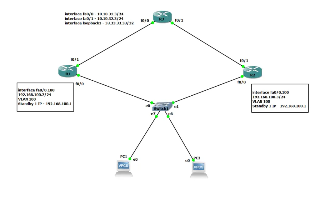
Let’s start by configuring our HSRP cisco setup. For this demonstration, I have used a simplified GNS3 network setup shown below.
Startup Configuration
Routers Interface Configuration mode.
configure terminal
interface FastEthernet0/0.100
encapsulation dot1q 100
ip address 192.168.100.2 255.255.255.0
interface FastEthernet0/0.200
encapsulation dot1q 200
ip address 192.168.200.2 255.255.255.0
int F0/0
no shutdown
interface FastEthernet0/1
ip address 10.10.31.1 255.255.255.0
Routers Interface Configuration mode.
Configure Terminal
interface FastEthernet0/0.100
encapsulation dot1q 100
ip address 192.168.100.3 255.255.255.0
interface FastEthernet0/0.200
encapsulation dot1q 200
ip address 192.168.200.3 255.255.255.0
int F0/0
no shutdown
interface FastEthernet0/1
ip address 10.10.32.2 255.255.255.0
no shutdown
interface Loopback1
ip address 33.33.33.33 255.255.255.255
!
interface FastEthernet0/0
ip address 10.10.31.3 255.255.255.0
no shutdown
!
interface FastEthernet0/1
ip address 10.10.32.3 255.255.255.0
no shutdown
PC1 is in Vlan 100, and IP address is 192.168.100.10/24, and the gateway is 192.168.100.1
PC1> ip 192.168.100.10/24 192.168.100.1
Checking for duplicate address…
PC1 : 192.168.100.10 255.255.255.0 gateway 192.168.100.1
PC2 is also in Vlan 100, and IP address is 192.168.100.11/24, and the gateway is 192.168.100.1
PC2> ip 192.168.100.11/24 192.168.100.1
Checking for duplicate address…
PC2 : 192.168.100.11 255.255.255.0 gateway 192.168.100.1
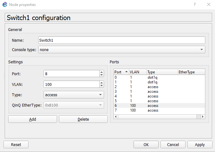
Here is the layer2 switch config in GNS3.
Here ports 6 and 7 are part of Vlan 100. And ports 0 and 1 are in the trunk and have dot1q encapsulation connected to R1 and R2, respectively.
Now let’s configure R1 and R2. I am using the standby group number as 1 and the virtual IP 192.168.100.1 on both routers inside the sub-interface configuration command.
R1 and R2 HSRP Configuration
R1(config-if)#int G0/0.100
R1(config-subif)#standby 1 ip 192.168.100.1
R2(config-if)#int G0/0.100
R2(config-subif)#standby 1 ip 192.168.100.1
If logs are enabled on the Cisco router, you will see different state change notifications. This will confirm that our devices are configured properly.
Router-1 changes its state from Speak to Standby to Listen and then finally elects to be “standby.”
R1 State Change Notifications
%HSRP-5-STATECHANGE: FastEthernet0/0.100 Grp 1 state Speak -> Standby
%HSRP-5-STATECHANGE: FastEthernet0/0.100 Grp 1 state Standby -> Listen
%HSRP-5-STATECHANGE: FastEthernet0/0.100 Grp 1 state Speak -> Standby
Router-2 changes its state as well from Speak to Standby and then Standby to Active. And then finally announces itself to be “Active.” Normally, when you do not configure any priority, the configured interface with the highest IP address becomes Active.
R2 State Change Notifications
%HSRP-5-STATECHANGE: FastEthernet0/0.100 Grp 1 state Speak -> Standby
%HSRP-5-STATECHANGE: FastEthernet0/0.100 Grp 1 state Standby -> Active
A ping from PC-1 at this point should be successful.
PC1> ping 192.168.100.1
84 bytes from 192.168.100.1 icmp_seq=1 ttl=255 time=16.309 ms
84 bytes from 192.168.100.1 icmp_seq=2 ttl=255 time=16.848 ms
84 bytes from 192.168.100.1 icmp_seq=3 ttl=255 time=16.688 ms
84 bytes from 192.168.100.1 icmp_seq=4 ttl=255 time=15.800 ms
84 bytes from 192.168.100.1 icmp_seq=5 ttl=255 time=16.775 ms
Let us check ARP details on Routers.
R2#sh IP arp | inc 100.1
Internet 192.168.100.10 0 0050.7966.6800 ARPA FastEthernet0/0.100
Internet 192.168.100.1 – 0000.0c07.ac01 ARPA FastEthernet0/0.100 –> Since R2 is HSRP Active router, you will be HSRP virtual MAC displayed on R2 only.
Check ARP on R1.
R1#sh ip arp
Protocol Address Age (min) Hardware Addr Type Interface
Internet 192.168.100.2 – c401.1a84.0000 ARPA FastEthernet0/0.100
Internet 192.168.100.3 23 c402.6f9c.0000 ARPA FastEthernet0/0.100
Internet 192.168.200.2 – c401.1a84.0000 ARPA FastEthernet0/0.200
Internet 192.168.200.3 23 c402.6f9c.0000 ARPA FastEthernet0/0.200
Let’s use the show standby command on R1 and R2 to check details.
R2#show standby
FastEthernet0/0.100 – Group 1
State is Active
2 state changes, last state change 00:23:44
Virtual IP address is 192.168.100.1
Active virtual MAC address is 0000.0c07.ac01 –> This HSRP virtual MAC address.
Local virtual MAC address is 0000.0c07.ac01 (v1 default)
Hello time 3 sec, hold time 10 sec
Next hello sent in 0.640 secs
Preemption disabled
Active router is local
Standby router is 192.168.100.2, priority 100 (expires in 7.388 sec)
Priority 100 (default 100)
IP redundancy name is “hsrp-Fa0/0.100-1” (default)
The default version of HSRP is v1.
HSRP default priority is 100.
Virtual mac is 0000.0c07.ac01
Preemption is disabled by default.
Now let’s check on R1.
R1#show standby
FastEthernet0/0.100 – Group 1
State is Standby
3 state changes, last state change 00:23:27
Virtual IP address is 192.168.100.1
Active virtual MAC address is 0000.0c07.ac01 –> This HSRP virtual MAC address.
Local virtual MAC address is 0000.0c07.ac01 (v1 default)
Hello time 3 sec, hold time 10 sec
Next hello sent in 0.616 secs
Preemption disabled
Active router is 192.168.100.3, priority 100 (expires in 6.908 sec)
Standby router is local
Priority 100 (default 100)
IP redundancy name is “hsrp-Fa0/0.100-1” (default)
Let us change some of the things based on the design recommendation from cisco.
Enable version 2 on both routers.
R1(config-subif)#standby version 2
R2(config-subif)#standby version 2
Enable Preemption on both routers
R1(config-subif)#standby 1 preempt
R2(config-subif)#standby 1 preempt
Quick Tip:- You can check the changed version and preemption by the “show standby” Command.
How to configure HSRP Priority
Next, change the default priority(100) on router R1 and make it an active router.
R1 default Priority Change
R1(config-subif)#standby 1 priority 110
You will see the below message on the console, changing the state from standby to active state. Now, R1 is Active since it has the highest priority among R1 (now 110) and R2 (100).
R1 will become an Active Router
%HSRP-5-STATECHANGE: FastEthernet0/0.100 Grp 1 state Standby -> Active
Let’s check this with another useful command, “Show standby Brief.”
R1#show standby brief
P indicates configured to preempt.
|
Interface Grp Prio P State Active Standby Virtual IP
Fa0/0.100 1 110 P Active local 192.168.100.3 192.168.100.1
Now R1 router is local. Let’s confirm this on R2 as well.
R2#show standby brief
P indicates configured to preempt.
|
Interface Grp Prio P State Active Standby Virtual IP
Fa0/0.100 1 100 P Standby 192.168.100.2 local 192.168.100.1
Since we have changed the active router to R1 now, let us check from PC1 whether we can ping the Virtual gateway or not.
PC1> ping 192.168.100.1
84 bytes from 192.168.100.1 icmp_seq=1 ttl=255 time=15.919 ms
And it is working., which is all hunky-dory.
Testing of the Setup
It is always advisable to test our setup.
Let’s shut down the R1 Fa0/0 router interface while continuously pinging 192.168.100.1 from PC1.
R1 LAN side Interface shutdown
R1(config)#int fa0/0
R1(config-if)#shutdown
There were no drops from PC1, but you may see 1 or 2 drops in an actual production network.
You will see the below messages on the console on R1.
Console messages on R1 and R2
R1#
%HSRP-5-STATECHANGE: FastEthernet0/0.100 Grp 1 state Active -> Init
And on R2.
R2#
%HSRP-5-STATECHANGE: FastEthernet0/0.100 Grp 1 state Standby -> Active
Let’s enable R1 fa0/0 and check whether “preemption” is working properly or not.
R1 LAN side interface no shutdown
R1(config-if)#int fa0/0
R1(config-if)#no shutdown
You will following message on the console, which confirms that R1 is Active now for Fa0/0.100
R1 regains its Active status, thanks to preemption configured under the interface
%HSRP-5-STATECHANGE: FastEthernet0/0.100 Grp 1 state Listen -> Active
HSRP Tracking feature
We will be extending our network setup and will use R3 as a WAN connection to showcase the tracking feature.
Let us test a scenario when our Primary WAN link connected to R3 from R1 fails.
We definitely want our Active router to change from R1 to R2 automatically in this case.
We will use the Object tracking feature, which basically monitors an interface/IP and reduces the priority of the Active router (R1) to make it less preferable than the secondary router (R2).
Let us configure and test it.
The first step is to configure our track to monitor the Fa0/1 line protocol in global configuration mode.
Configuring track on R1 to monitor WAN Interface
R1(config)#track 1 ?
interface Select an interface to track
ip IP protocol
list Group objects in a list
rtr Response Time Reporter (RTR) entry
R1(config)#track 1 interface fastEthernet 0/1 ?
ip IP parameters
line-protocol Track interface line-protocol
R1(config)#track 1 interface fastEthernet 0/1 line-protocol
And then, the next step is to attach the track to HSRP group 1 under the Fa0/0.100 sub-interface configuration mode.
Applying track under R1 sub-interface
R1(config)#int fa0/0.100
R1(config-subif)#standby 1 track 1 decrement 50
Let us check the status on R1.
R1#sh standby brief
P indicates configured to preempt.
|
Interface Grp Prio P State Active Standby Virtual IP
Fa0/0.100 1 110 P Active local 192.168.100.3 192.168.100.1
Fa0/0.100 2 100 P Standby 192.168.100.3 local 192.168.100.100
R1 is Active for HSRP group 1 on R1.
Now let’s test it by shutting down Interface fa0/1 on R1.
R1 WAN Interface down
R1(config)#int fa0/1
R1(config-if)#shutdown
You will see the following message on the R1 console.
R1 Changes its status to Standby
%TRACKING-5-STATE: 1 interface Fa0/1 line-protocol Up->Down
%HSRP-5-STATECHANGE: FastEthernet0/0.100 Grp 1 state Active -> Speak
%LINK-5-CHANGED: Interface FastEthernet0/1, changed state to administratively down
%LINEPROTO-5-UPDOWN: Line protocol on Interface FastEthernet0/1, changed state to down
%HSRP-5-STATECHANGE: FastEthernet0/0.100 Grp 1 state Speak -> Standby
Let’s Check the status on R1. You can see that now R1 is acting as standby.
R1#sh standby brief
P indicates configured to preempt.
|
Interface Grp Prio P State Active Standby Virtual IP
Fa0/0.100 1 60 P Standby 192.168.100.3 local 192.168.100.1 –> R2 is Active now
Fa0/0.100 2 100 P Standby 192.168.100.3 local 192.168.100.100
Let’s test this setup from a workstation (VPCS-1) point of view as well.
Now trace to R3’s loopback interface is landing up to R2 in this case, which is perfect as R2 is Active for group 1 now.
PC1> trace 33.33.33.33
trace to 33.33.33.33, 8 hops max, press Ctrl+C to stop
1 192.168.100.3 15.594 ms 15.695 ms 15.908 ms –> The ip traffic is traversing R2 now.
2 * * *
P.S – Don’t worry about the ICMP failures, because there is no reverse route from R3 to VPCS-1 ip address, the reverse traffic will fail.
How to configure Advanced Multiple HSRP config for load balancing
In Hot Standby Router Protocol, load balancing is achieved by using multiple HSRP groups. Routers configured for HSRP can belong to multiple groups and multiple VLANs. By configuring one group to be active for R1 and standby for R2, and the second group to be active for R2 and standby for R1, both routers R1 and R2 can be used to pass ip traffic, as opposed to one sitting idle.
R1 serves all Vlan 100 clients in this normal operation while R2 monitors and waits for R1 to failover. This is not a very good use of resources. Now let’s spice up our HSRP config by doing load-balancing across due routers within the same VLAN 100.
First, change the PC2 gateway to 192.168.100.100, which we will configure in our next step.
PC2 gateway change
PC2> ip 192.168.100.11/24 192.168.100.100
Checking for duplicate address…
PC1 : 192.168.100.11 255.255.255.0 gateway 192.168.100.100
Now let us configure a new HSRP group 2 on R1 and R2 within the same sub-interface (fa0/0.100) to support our Multiple HSRP design. This time, we will make R2 an Active router for group 2.
R1 is Standby and R2 is Active for HSRP Standby group 2
R1(config-if)#int fa0/0.100
R1(config-subif)#standby 2 ip 192.168.100.100
R1(config-subif)#standby 2 preempt
R2(config)#int fa0/0.100
R2(config-subif)#standby 2 ip 192.168.100.100
R2(config-subif)#standby 2 preempt
R2(config-subif)#standby 2 priority 120
You will see notifications on the console, and now R2 is an Active router.
R2 is Active for HSRP Group 2
%HSRP-5-STATECHANGE: FastEthernet0/0.100 Grp 2 state Speak -> Standby
%HSRP-5-STATECHANGE: FastEthernet0/0.100 Grp 2 state Standby -> Active
Let’s ping 192.168.100.100 from PC2 and confirm.
PC2> ping 192.168.100.100
84 bytes from 192.168.100.100 icmp_seq=1 ttl=255 time=16.485 ms
Wow, our setup is working.
Let’s recap what we have done so far.
- PC1 and PC2 in VLAN 100.
- PC1 is pointing towards R1 and PC2 towards R2.
- I have added R3 in this setup to prove that this setup is working as expected.
- PC1 is going through R1, which has Fa0/0.100 ip configured as 192.168.100.2
PC1> trace 33.33.33.33
trace to 33.33.33.33, 8 hops max, press Ctrl+C to stop
1 192.168.100.2 16.406 ms 16.579 ms 16.799 ms
2 *192.168.100.2 16.128 ms (ICMP type:3, code:1, Destination host unreachable)
- PC2 is going through R2, which has Fa0/0.100 ip configured as 192.168.100.3
PC2> trace 33.33.33.33
trace to 33.33.33.33, 8 hops max, press Ctrl+C to stop
1 192.168.100.3 16.179 ms 16.429 ms 15.951 ms
2 *192.168.100.3 15.336 ms (ICMP type:3, code:1, Destination host unreachable)
Don’t worry about the (Destination Host unreachable) message; it has appeared because there is no reverse route configured from R3.
How to make HSRP more secure with Authentication
You can also secure the HSRP protocol by configuring Authentication. I will not go deep into this topic as it is comparatively easy, and once you understand the basic functionality and use case of HSRP, you will get the hang of it.
HSRP includes an authentication mechanism. You can opt for either plaintext or MD5. Follow these steps to configure MD5:
R1 & R2
R1 and R2 Authentication configuration
(config)#interface Fa0/0.100
(config-subif)#standby 1 authentication md5 key-string CISCO_KEY
This guarantees authentication of all packets that are sent between the two routers. This prohibits anyone from joining our HSRP configuration on the 192.168.100.0/24 subnet.
How to make HSRP more responsive with Timers
By default, HSRP is somewhat a slow protocol, as it has 10 seconds of hold-time time before the standby router takes over the active role. Therefore, you should always tweak it to match your company’s SLA.
Let us configure hello time to 50 milliseconds and the hold time to 150 milliseconds.
R1 and R2 HSRP Timer configuration
R1(config-subif)#standby 1 timers ?
<1-254> Hello interval in seconds
msec Specify hello interval in milliseconds
(config)#interface fa0/0.100
(config-subif)#standby 1 timers msec 50 msec 150
You can check by this show standby command.
R1 & R2
show standby | include time
Hello time 50 msec, hold time 150 msec
Common Troubleshooting steps with HSRP
Sometimes things do not work been even if you have taken all necessary steps to configure HSRP properly. For those times , be mindful of these steps when facing any HSRP related issue –
- Check if HSRP routers are on the same network segment.
- Check HSRP virtual ip is configured as gateway ip on hosts.
- Check HSRP configuration on both routers for any mismatch on VLANs, ip subnets, standby groups, virtual ips etc.
- Check if VLANs are allowed between two Devices where HSRP is configured. Especially when there is a layer2 switch in between.
Check if the interface is enabled.
Useful commands for HSRP Config Cisco
show standby –> The command show standby can be used to display detailed information about HSRP groups of which a switch is a member. This command would not provide a quick view. This command displays information about HSRP on all configured interfaces and for all HSRP groups. It also displays hello timer information and the expiration timer for the standby switch.
show standby brief –> The command show standby brief should be used to quickly view the HSRP state of a cisco router or a switch for all HSRP groups of which it is a member. The summary information it provides includes the group number, priority, state, active device address, standby address, and group address.
show ip interface brief –> The command show ip interface brief is useful in that lists the interfaces and displays the basic IP configuration of each. This output would include the IP address of the interface and the state of the interface, but not HSRP information.
Debug standby –> Shows all HSRP related errors, events, packets, and state transitions.
show run –> Displays the entire configuration of the cisco device.
Definitions and Acronyms used in the post
HSRP – Hot Standby Router Protocols
FHRP – First Hop Redundancy Protocol
Quiz
Conclusion
In this post, we have looked into HSRP protocol configuration, which provides gateway level redundancy for uninterrupted network connectivity when any single gateway fails. Furthermore, we have enhanced our configuration by providing load balancing traffic among two routers by Multiple HSRP.
If you liked this post, please share it to reach out to other people who might be searching for the same topic.
- pfSense 10G Home Lab Setup: Complete Hardware Guide (2026) - April 1, 2026
- Best Budget Home Lab Setup Under $300 (2026): Complete Starter Stack - March 30, 2026
- Best Modems for Spectrum: Top DOCSIS 3.1 Picks That Actually Work - March 28, 2026