The router on a stick configuration is a powerful and efficient way to design your network, especially when you need to manage traffic between different virtual LANs (VLANs). This method makes it easy to add new network segments without running a dedicated physical cable for each one back to your routing device. It’s a cost-effective solution for enabling communication between isolated network groups.
What is Router on a Stick?
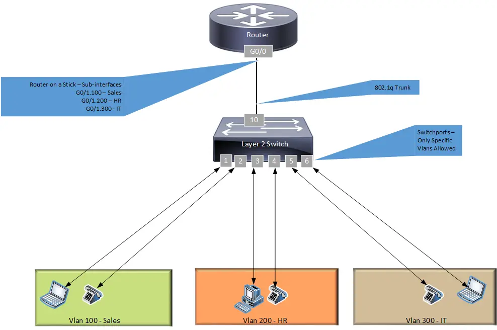
Router on a Stick (ROAS) is a network design method used to route traffic between multiple VLANs on a network. It involves connecting a router and a switch using a single physical link, which is configured as an 802.1q trunk. The router handles all inter-VLAN communication by using virtual sub-interfaces, with one sub-interface configured for each VLAN it needs to service.
Router on a Stick Configuration Scenarios
This post will discuss two common scenarios where this configuration is used: in an Enterprise network and a Service Provider network. We’ll use a Cisco router and a Cisco switch for our examples, but the underlying logic is the same across different vendors. You should always check your specific vendor’s documentation for exact command syntax. Let’s dive into the setup and configuration.
Router on a Stick Config – Enterprise Example
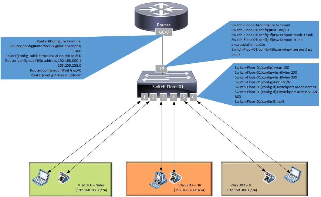
In this example, we have a typical office setup with multiple departments. Each department is assigned to a separate VLAN and has its own IP address block. For simplicity, each department has two ports reserved on a Layer 2 switch.
- Ports 1 & 2 – VLAN 100 – Sales – 192.168.100.0/24
- Ports 3 & 4 – VLAN 200 – HR – 192.168.200.0/24
- Ports 5 & 6 – VLAN 300 – IT – 192.168.300.0/24
When a user in the Sales department wants to communicate with another user in the same department, their traffic stays within VLAN 100 and doesn’t need a router. However, when a Sales user needs to access a resource in the IT department (VLAN 300), the traffic must be sent to a Layer 3 device for routing. This is accomplished by configuring a Default Gateway on the user’s device.
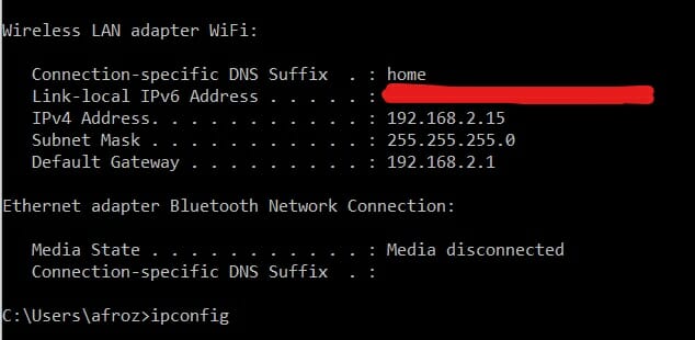
(Bonus Tip) – You can see this in action on your own computer. Open a command prompt (Windows) or terminal (macOS/Linux) and type ipconfig (on Windows) or ifconfig / ip addr (on macOS/Linux). You’ll see your device’s IP address, its subnet mask, and the Default Gateway. This gateway is the router’s address that your computer sends traffic to when it needs to reach a different network, like the internet or another VLAN.
To make this work, the Layer 2 switch is connected to a Layer 3-capable router via a single link (fiber or copper), which is configured as an 802.1q trunk. On the router, the single physical port is logically divided into multiple sub-interfaces. Each sub-interface is assigned to a specific VLAN and given an IP address, which serves as the default gateway for all devices in that VLAN.
Now, let’s configure each device. Note that commands can vary based on the Cisco IOS version you are using.
STEP 1 – Switch Configuration
First, we will configure the switch port connected to the router as an 802.1q trunk link. We’ll use GigabitEthernet0/10 for this connection, as FastEthernet is outdated for modern networks.
Switch Trunk Port Configuration
- Switch-Floor-01#configure terminal
- Switch-Floor-01(config)#interface GigabitEthernet0/10
- Switch-Floor-01(config-if)#switchport mode trunk
- Switch-Floor-01(config-if)#spanning-tree portfast trunk
Note: On modern Cisco switches, the switchport trunk encapsulation dot1q command is often unnecessary as 802.1Q is the default and only supported trunking protocol. We’ve omitted it from this updated configuration.
Next, let’s create the required VLANs and configure the access ports for user devices.
VLAN and Access Port Configuration
- Switch-Floor-01#configure terminal
- Switch-Floor-01(config)#vlan 100
- Switch-Floor-01(config-vlan)#name Sales
- Switch-Floor-01(config-vlan)#vlan 200
- Switch-Floor-01(config-vlan)#name HR
- Switch-Floor-01(config-vlan)#vlan 300
- Switch-Floor-01(config-vlan)#name IT
- Switch-Floor-01(config-vlan)#exit
- Switch-Floor-01(config)#interface range GigabitEthernet0/1 – 2
- Switch-Floor-01(config-if-range)#switchport mode access
- Switch-Floor-01(config-if-range)#switchport access vlan 100
- Switch-Floor-01(config-if-range)#exit
- Switch-Floor-01(config)#interface range GigabitEthernet0/3 – 4
- Switch-Floor-01(config-if-range)#switchport mode access
- Switch-Floor-01(config-if-range)#switchport access vlan 200
- Switch-Floor-01(config-if-range)#exit
- Switch-Floor-01(config)#interface range GigabitEthernet0/5 – 6
- Switch-Floor-01(config-if-range)#switchport mode access
- Switch-Floor-01(config-if-range)#switchport access vlan 300
- Switch-Floor-01(config-if-range)#exit
STEP 2 – Router Configuration
In this configuration, we use a single physical interface on the Cisco router (GigabitEthernet0/1) to support all VLANs. We create one sub-interface for each VLAN and set the encapsulation type to 802.1q to match the trunk on the switch. It’s highly recommended to use a Gigabit Ethernet port to ensure you have enough bandwidth for inter-VLAN traffic.
Router Sub-Interface Configuration
- R#configure terminal
- R(config)#interface GigabitEthernet0/1.100
- R(config-subif)#description Gateway for Sales VLAN
- R(config-subif)#encapsulation dot1Q 100
- R(config-subif)#ip address 192.168.100.1 255.255.255.0
- R(config-subif)#exit
- R(config)#interface GigabitEthernet0/1.200
- R(config-subif)#description Gateway for HR VLAN
- R(config-subif)#encapsulation dot1Q 200
- R(config-subif)#ip address 192.168.200.1 255.255.255.0
- R(config-subif)#exit
- R(config)#interface GigabitEthernet0/1.300
- R(config-subif)#description Gateway for IT VLAN
- R(config-subif)#encapsulation dot1Q 300
- R(config-subif)#ip address 192.168.300.1 255.255.255.0
- R(config-subif)#exit
- R(config)#interface GigabitEthernet0/1
- R(config-if)#no shutdown
STEP 3 – Verification Commands
After applying the configuration, use these commands to check if your setup is working properly.
Router Show Commands
show ip interface brief→ Checks the status and IP address of all interfaces.show ip route→ Displays the router’s routing table.show running-config interface GigabitEthernet0/1→ Shows the configuration for the physical interface and all its sub-interfaces.
Switch Show Commands
show vlan brief→ Displays a summary of all VLANs and their assigned ports.show interfaces trunk→ Shows information about all trunking ports on the switch.show interfaces GigabitEthernet0/10 switchport→ Checks the operational mode of the trunk port.
Test the setup: To verify that inter-VLAN routing is working, go to a PC in the Sales VLAN (100) and try to ping a device in the IT VLAN (300). If the configuration is correct, the ping should be successful.
Router on a Stick Config – Service Provider Example
The Router on a Stick design is also common in Service Provider networks. It is often seen on Provider Edge (PE) routers, where a single router must provide connectivity for multiple customers. To conserve physical ports on the expensive PE router, a Layer 2 switch is used to aggregate customer connections, with each customer being isolated in their own VLAN.
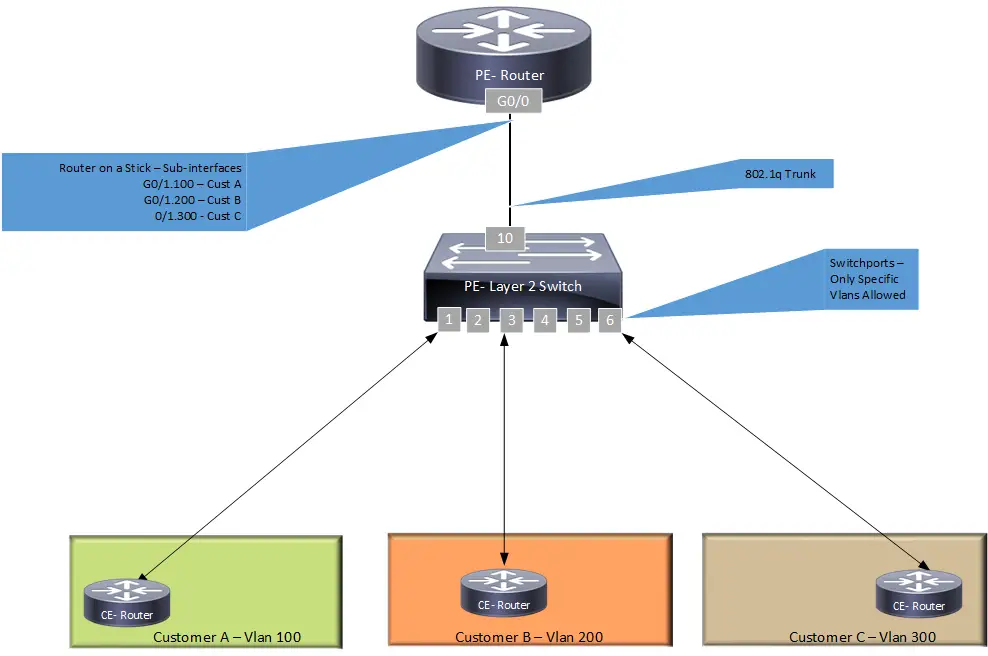
The overall network logic is the same as the enterprise example. However, in a multi-tenant environment, it is critical to prevent traffic from flowing between different customers. Service providers typically use Access Control Lists (ACLs) on the router’s sub-interfaces to enforce this security policy.
Service Provider Cisco Switch Configuration
SP Switch Configuration
- SP-Switch-01#configure terminal
- SP-Switch-01(config)#vlan 100
- SP-Switch-01(config-vlan)#name Customer_A
- SP-Switch-01(config-vlan)#vlan 200
- SP-Switch-01(config-vlan)#name Customer_B
- SP-Switch-01(config-vlan)#vlan 300
- SP-Switch-01(config-vlan)#name Customer_C
- SP-Switch-01(config-vlan)#exit
- SP-Switch-01(config)#interface GigabitEthernet0/1
- SP-Switch-01(config-if)#description “Connection for Customer A”
- SP-Switch-01(config-if)#switchport mode access
- SP-Switch-01(config-if)#switchport access vlan 100
- SP-Switch-01(config-if)#exit
- SP-Switch-01(config)#interface GigabitEthernet0/3
- SP-Switch-01(config-if)#description “Connection for Customer B”
- SP-Switch-01(config-if)#switchport mode access
- SP-Switch-01(config-if)#switchport access vlan 200
- SP-Switch-01(config-if)#exit
- SP-Switch-01(config)#interface GigabitEthernet0/6
- SP-Switch-01(config-if)#description “Connection for Customer C”
- SP-Switch-01(config-if)#switchport mode access
- SP-Switch-01(config-if)#switchport access vlan 300
- SP-Switch-01(config-if)#exit
- SP-Switch-01(config)#interface GigabitEthernet0/10
- SP-Switch-01(config-if)#description “Trunk to PE-Router_Gi0/1”
- SP-Switch-01(config-if)#switchport mode trunk
Service Provider Cisco Router Configuration
PE Router Configuration
- PE#configure terminal
- PE(config)#interface GigabitEthernet0/1.100
- PE(config-subif)#description “Link for Customer A”
- PE(config-subif)#encapsulation dot1Q 100
- PE(config-subif)#ip address 192.168.100.1 255.255.255.0
- PE(config-subif)#exit
- PE(config)#interface GigabitEthernet0/1.200
- PE(config-subif)#description “Link for Customer B”
- PE(config-subif)#encapsulation dot1Q 200
- PE(config-subif)#ip address 192.168.200.1 255.255.255.0
- PE(config-subif)#exit
- PE(config)#interface GigabitEthernet0/1.300
- PE(config-subif)#description “Link for Customer C”
- PE(config-subif)#encapsulation dot1Q 300
- PE(config-subif)#ip address 192.168.300.1 255.255.255.0
- PE(config-subif)#exit
- PE(config)#interface GigabitEthernet0/1
- PE(config-if)#description “Trunk from SP-Switch-01”
- PE(config-if)#no shutdown
Limitations of Router on a Stick
While effective, the ROAS design has two primary limitations you should be aware of:
- Single Point of Failure: The single physical link between the router and the switch is a critical failure point. If that link or the router’s physical port goes down, all inter-VLAN communication will stop.
- Bandwidth Bottleneck: All traffic between VLANs must travel up the trunk link to the router and back down again. This can create a performance bottleneck, especially in networks with heavy inter-VLAN traffic, as the link’s bandwidth is shared by all VLANs.
Router on a Stick vs. Layer 3 Switch
For networks with higher performance and availability requirements, a Layer 3 switch is often the preferred alternative to Router on a Stick. A Layer 3 switch can perform both Layer 2 switching and Layer 3 routing, routing traffic between VLANs at hardware speed using internal virtual interfaces (SVIs). Here’s a quick comparison:
| Aspect | Router on a Stick | Layer 3 Switch |
|---|---|---|
| Performance | Lower throughput; potential bottleneck at the trunk link. | Higher throughput; routing at wire speed. |
| Scalability | Limited by the router’s processing power and trunk bandwidth. | Highly scalable; easily handles many VLANs and high traffic volumes. |
| Cost | Lower initial cost; uses existing router and a Layer 2 switch. | Higher initial cost for the Layer 3 switch. |
| Configuration | Configuration is split between two devices (router and switch). | Configuration is centralized on a single device. |
Common Network Terminology
- DTE – Data Terminal Equipment (e.g., a user PC, phone, or any end-user device).
- DCE – Data Communications Equipment (e.g., a switch or a router that provides connectivity).
- Router – A Layer 3 device used to connect different networks, VLANs, or IP subnets. It operates at the Network layer of the OSI model.
- Switch – A Layer 2 device used to connect multiple devices within the same network. It operates at the Data Link layer of the OSI model.
- VLAN – A Virtual Local Area Network is a group of devices partitioned and isolated as if they were on their own separate physical network. A router or Layer 3 device is required for communication between different VLANs.
- PE – Provider Edge router.
- CE – Customer Edge device.
Remember to check more MPLS-related terminologies and MPLS VPN scenarios posts for more information on these topics.
Frequently Asked Questions (FAQ)
Why is it called ‘Router on a Stick’?
The name is a visual metaphor. In network diagrams, the single link connecting the router to the switch looks like a ‘stick’, with the router sitting on top of it, serving all the VLANs below.
How many VLANs can a single trunk support?
A standard 802.1Q trunk can theoretically support up to 4,094 VLANs. However, in a Router on a Stick design, the practical limit is determined by the router’s processing power and the available bandwidth on the trunk link.
What happens if the physical router interface goes down?
If the physical interface on the router fails, all of its sub-interfaces will also go down. This will sever the connection to the switch, and all inter-VLAN communication will cease. This highlights why the link is a single point of failure.
Article Summary
In this post, we covered the Router on a Stick configuration using an up-to-date Cisco switch and router example. We demonstrated how to use a single router interface to provide inter-VLAN routing services in environments without Layer 3 switches. We also discussed the use cases in service provider networks, the limitations of the design, and how it compares to using a Layer 3 switch.
If you found this information valuable, please share it with others using the share buttons at the top left of the post. Sharing our articles takes about a minute and helps afrozahmad.com Blog reach more people.
- Best Routers for AT&T Fiber Internet (Tested for IP Passthrough) - March 26, 2026
- Best PoE Switches for Home Lab and Small Business (2026) - March 25, 2026
- Best Routers for T-Mobile Home Internet in 2026 (Tested Behind the Gateway) - March 19, 2026