TL;DR Cisco vPC (virtual Port Channel) lets a device build one logical port channel to two upstream Nexus switches for active-active links, bandwidth aggregation, and fast failover—without blocking ports in STP.
Why use it: active-active redundancy, no STP blocking, full uplink utilization, fast convergence. Quick checklist: same supported Nexus models for each peer, build a resilient peer link (or fabric peering in VXLAN EVPN), set up a separate peer keepalive path, enable peer-gateway/peer-switch where appropriate, and verify Type-1 consistency before going live.
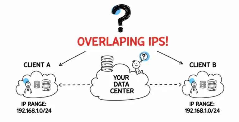
Before we dive into what Cisco vPC (virtual Port Channel) is, let’s start with the basics. A standard port channel is a long-standing technology that bundles multiple physical interfaces into a single logical link. This provides excellent benefits like increased bandwidth, load balancing, and redundancy. However, it has one major limitation: all links in the bundle must terminate on the same physical switch. If that single device fails, you lose all connectivity.
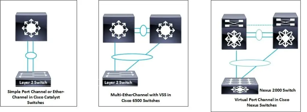
To overcome this single point of failure, Cisco introduced technology to allow a port channel to span across two different physical switches. The first iteration of this was the Virtual Switching System (VSS) on the classic Catalyst 6500 series. VSS merged two switches into a single logical entity, sharing one control and management plane. This was a game-changer for network resiliency.
In 2009, Cisco evolved this concept with the launch of vPC for its Nexus series of data center switches. While the goal is similar to VSS, the architecture is fundamentally different. With vPC, each Nexus switch maintains its own independent control plane. They are managed as two separate devices but work together to present a single logical port channel to a downstream device. This dual control plane design is a key differentiator, offering robust high availability without the complexities of a merged chassis system.
Today, the modern equivalent to VSS on the Catalyst 9000 series platform is Cisco StackWise Virtual, which also uses a single control plane architecture, distinguishing it from the dual control plane approach of vPC on Nexus switches.
In simple terms, vPC enables a server, switch, or any other device to create a port channel that connects to two separate upstream Nexus switches. This allows for the creation of Layer 2 multipathing, which provides excellent redundancy and doubles the usable bandwidth by eliminating links blocked by Spanning Tree Protocol (STP).
Cisco vPC Benefits
The advantages of implementing Cisco vPC in your data center are significant:
- Allows a single device to use a port channel across two upstream switches.
- Eliminates Spanning Tree Protocol (STP) blocked ports.
- Provides a loop-free topology.
- Uses all available uplink bandwidth.
- Provides fast convergence if a link or an entire device fails.
- Delivers excellent link-level and device-level resiliency.
- Ensures high availability for connected devices.
Key vPC Terminology
Understanding the components of a vPC architecture is key to a successful deployment.
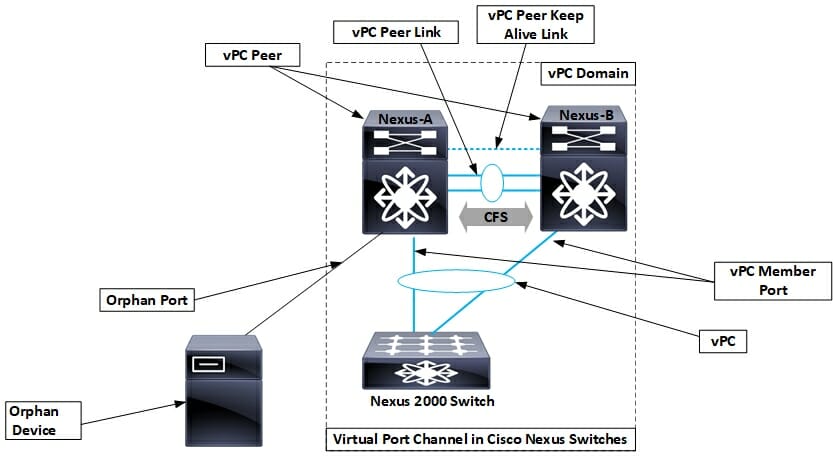
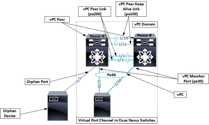
- vPC Domain: This is a logical grouping of the two vPC peer switches, the vPC peer link, and all the vPC port channels connected to downstream devices. Ensure the vPC domain ID is unique within your contiguous Layer 2 domain/fabric.
- vPC Peer Switch: One of the two Cisco Nexus switches connected by the peer link. One switch will be elected as the primary and the other as the secondary.
- vPC Peer Link: This is the most critical component. It is a dedicated link (typically a port channel with multiple high‑bandwidth members such as 25G/100G/400G) used to synchronize state information, carry control plane traffic, and transport multicast/broadcast/unknown unicast data between the two peer switches.
- vPC Peer Keepalive Link: This is a separate link that provides a heartbeat between the two peer switches. It is used as a secondary check to determine if the peer is truly down or if only the peer link has failed, which helps prevent split-brain scenarios.
- vPC Member Port: An interface on a peer switch that belongs to a vPC port channel.
- Orphan Port: An interface on a vPC peer switch that is connected to a single-homed device (not part of a vPC).
Cisco vPC Requirements
- vPC is a foundational feature supported on modern Cisco Nexus switch platforms and is included in base NX-OS.
- For a supported vPC domain on Nexus 9000: peers must be identical, supported models. For 9300 series, both peers must be the exact same model. For 9500 series, line cards, supervisors, fabric modules, and controllers must match and peer-link members should be on the same model/slots on each chassis.
How to Configure Cisco vPC
Configuring vPC is straightforward if you follow the correct order of operations. The following steps will guide you through the process.
Please note: The order of these steps is important.
- Enable necessary features.
- Create the vPC domain.
- Configure the vPC Peer Keepalive link.
- Create the vPC Peer Link.
- Create vPC member ports.
- Verify configuration consistency.
Step 1: Enable Features
You must enable the vpc and lacp features on both Nexus switches.
Nexus-A and B
feature vpc
feature lacp
Step 2: Create the vPC Domain
Define the vPC domain with a unique ID (1-1000). Set priorities for both switches; the switch with the lower priority value becomes the primary.
Nexus-A (Primary)
vpc domain 1
 role priority 8192
 peer-switch
 peer-gateway
Nexus-B (Secondary)
vpc domain 1
 role priority 16384
 peer-switch
 peer-gateway
Step 3: Configure the Peer Keepalive Link
Use either out-of-band management or a routed in-band path. The mgmt0 interface always belongs to the management VRF and cannot be moved to a user VRF. If using data-plane links for keepalive, place them in a dedicated user VRF. Avoid sending keepalive over the peer-link.
Nexus-A
! Option A: Use mgmt0 (management VRF)
vrf context management
interface mgmt0
  ip address 10.1.1.1/30
vpc domain 1
  peer-keepalive destination 10.1.1.2 source 10.1.1.1 vrf management

! Option B: Use routed front-panel links in a user VRF
vrf context VPC_PKAL
interface ethernet1/50
  no switchport
  vrf member VPC_PKAL
  ip address 172.16.1.1/30
vpc domain 1
  peer-keepalive destination 172.16.1.2 source 172.16.1.1 vrf VPC_PKAL
Nexus-B
! Option A: Use mgmt0 (management VRF)
vrf context management
interface mgmt0
  ip address 10.1.1.2/30
vpc domain 1
  peer-keepalive destination 10.1.1.1 source 10.1.1.2 vrf management

! Option B: Use routed front-panel links in a user VRF
vrf context VPC_PKAL
interface ethernet1/50
  no switchport
  vrf member VPC_PKAL
  ip address 172.16.1.2/30
vpc domain 1
  peer-keepalive destination 172.16.1.1 source 172.16.1.2 vrf VPC_PKAL
Step 4: Create the vPC Peer Link
Create a port channel between the two switches and configure it as the vPC peer link. Use multiple high-bandwidth members and distribute across hardware where possible.
Nexus-A & B
interface Ethernet1/1-2
 description vPC Peerlink Member
 channel-group 200 mode active
interface port-channel200
 description vPC Peerlink
 switchport mode trunk
 spanning-tree port type network
 vpc peer-link
Step 5: Create vPC Member Ports
Finally, configure the downstream-facing interfaces. The port channel number and the VPC ID must match on both peer switches. vPC supports LACP or static port channels; LACP active is recommended.
Nexus-A & B
interface Ethernet1/20
 description Link to Server-1
 channel-group 30 mode active
interface port-channel30
 description Server-1 LAG
 switchport mode trunk
 vpc 30
The last step is to configure a standard LACP port channel (recommended) or a static channel-group on the downstream device (e.g., your server).
Step 6: Verify Configuration Consistency
Use the following command to check for any configuration mismatches between the peer switches for a specific vPC.
Nexus-A & B
show vpc consistency-parameters vpc 30
!
! Expect Type-1 (critical) parameters to match (mode, speed, duplex, port mode,
! native VLAN, MTU). Type-2 mismatches do not suspend the vPC.
!
Important Commands to Verify and Troubleshoot vPC
Once configured, you’ll need a few key commands to verify the health of your vPC domain.
show vpc brief
This is your primary command for a high-level overview. Look for ‘peer adjacency formed ok’ for the Peer status and ‘peer is alive’ for the keep-alive status. You also want to see ‘success’ for the consistency status.
Example Output
Nexus-B# show vpc brief
Legend:
(*) - local vPC is down, forwarding via vPC peer-link
vPC domain id                   : 1
Peer status                     : peer adjacency formed ok
vPC keep-alive status           : peer is alive
Configuration consistency status: success
Per-vlan consistency status     : success
Type-2 consistency status       : success
vPC role                        : secondary
Number of vPCs configured       : 1
Peer Gateway                    : Enabled
Dual-active excluded VLANs      : -
Graceful Consistency Check      : Enabled
Auto-recovery status            : Enabled (timeout = 240 seconds)

vPC Peer-link status
---------------------------------------------------------------------
id   Port   Status Active vlans
--   ----   ------ ---------------------------------------------------
1    Po200  up     1,2,5,10

vPC status
----------------------------------------------------------------------------
id   Port   Status      Consistency Reason                     Active vlans
--   ----   --------    ----------- -------------------------- -----------
30   Po30   up          success     success                    10
show vpc orphan-ports
This command is useful for identifying any ports connected to single-homed devices. It’s important to know where these ports are, as they can lose connectivity if their local vPC peer switch goes down.
Example Output
Nexus-A# show vpc orphan-ports
Note:
--------::Going through port database. Please be patient.::--------
VLAN    Orphan Ports
------- -------------------------
900     Eth1/7
show vpc consistency-parameters
This command provides a detailed check of all Type 1 (critical) and Type 2 (non-critical) parameters. Any mismatch in Type 1 parameters will cause the vPC on the secondary peer to be suspended to prevent network instability.
Example Output
Nexus-A# show vpc consistency-parameters vpc 30
Legend:
  Type 1 : vPC will be suspended in case of mismatch
Name                      Type  Local Value      Peer Value
------------------------  ----  ---------------  ---------------
Mode (LACP)                1    active           active
Speed                      1    10 Gb/s          10 Gb/s
Duplex                     1    full             full
Port Mode                  1    trunk            trunk
Native VLAN                1    1                1
MTU                        1    1500             1500
Allowed VLANs             -     10               10
show vpc peer-keepalive
Finally, to check the detailed status of the keepalive link, use the show vpc peer-keepalive command. This will show you source/destination IPs, timers, and message statistics.
Example Output
Nexus-B# show vpc peer-keepalive
vPC keep-alive status           : peer is alive
--Peer is alive for             : (2900862) seconds, (249) msec
--Send status                   : Success
--Receive status                : Success
--Last update from peer         : (0) seconds, (192) msec
vPC Keep-alive parameters
--Destination                   : 10.1.1.1
--Keepalive interval            : 1000 msec
--Keepalive timeout             : 5 seconds
--Keepalive hold timeout        : 3 seconds
--Keepalive vrf                 : management
--Keepalive udp port            : 3200
--Keepalive tos                 : 192
Cisco vPC Best Practices
Use the below table as a guideline when configuring and deploying vPC in your network.
| Component | Recommendation | Reason |
|---|---|---|
| vPC Peer Keepalive | Use the management interface (mgmt0) in the management VRF, or a dedicated routed link in a user VRF. Keep it isolated from data-plane events. | Isolates keepalive traffic and avoids dependency on the peer-link or production VLANs. |
| vPC Peer Link | Use at least two high-bandwidth members (25G/100G/400G where available) in a port channel from different line cards if possible. | Provides headroom for state sync and failure traffic; protects against line card failure. |
| vPC Domain ID | Ensure the vPC domain ID is unique within your contiguous Layer 2 network. | Prevents conflicts with system MAC/LACP IDs and avoids unexpected blocking. |
| STP Priority | Set the vPC primary peer as the spanning-tree root for all VLANs and enable spanning-tree port type network on the peer-link (Bridge Assurance). | Ensures predictable traffic paths and fail-safe loop protection on the peer-link. |
| Orphan Ports | Identify single-homed devices. Where appropriate, configure vpc orphan-port suspend on those interfaces. |
Protects orphan devices during peer-link failures by intentionally suspending them on the secondary. |
Modern Applications: vPC in a VXLAN EVPN Fabric
While vPC is a Layer 2 technology, it remains highly relevant in modern data center fabrics based on VXLAN EVPN. In a typical leaf-spine architecture, servers or other devices at the edge of the network often require redundant connections.
vPC is the standard method for providing device-level redundancy at the leaf layer. Two leaf switches are configured as a vPC pair, and they act as a single logical VTEP (Anycast VTEP) using a VIP on the NVE loopback along with per-switch PIPs. With a Distributed Anycast Gateway, all leafs share the same anycast gateway MAC and IP per VLAN/SVI, and features like peer-gateway allow local forwarding without unnecessary peer-link traversal.
vPC Fabric Peering (Virtual Peer-Link over the Fabric)
Many modern Nexus 9300 platforms support vPC Fabric Peering, which builds a virtual peer-link across the VXLAN EVPN fabric instead of consuming physical ports between the pair. The control plane uses CFSoIP over the routed fabric, and data traffic between peers traverses VXLAN tunnels. This approach reduces cabling, improves resiliency, and adds state tracking tied to fabric uplinks. Check platform and release support before enabling and note feature limitations in complex topologies.
Layer 3 over vPC (overview)
Recent NX‑OS releases support routing adjacencies across vPC member ports. When using Layer 3 over vPC, ensure you enable peer-gateway and follow the documented caveats for your platform and software train.
Acronyms Used in This Post
- vPC: Virtual Port-Channel
- VSS: Virtual Switch System
- STP: Spanning Tree Protocol
- VXLAN: Virtual Extensible LAN
- EVPN: Ethernet VPN
- VTEP: VXLAN Tunnel Endpoint
Conclusion
In this article, we covered the history and architecture of Cisco vPC, its key benefits, and the components that make it work. We walked through a configuration example for the Nexus 9000 platform and highlighted the most important commands for verification and troubleshooting. We also touched on modern deployments, including Anycast VTEP, vPC Fabric Peering, and Layer 3 over vPC. By following these steps and best practices, you can build a highly resilient and efficient data center network. I hope you found this guide helpful; please feel free to share it and subscribe for more networking tips and news.
Frequently Asked Questions About Cisco vPC
What is a vPC orphan port?
A vPC orphan port is an interface on a vPC peer switch that is connected to a single-homed device (a device not using a port channel across both switches). If the switch hosting the orphan port fails, that device will lose connectivity. It’s a key consideration for migration and design. On supported platforms, you can configure vpc orphan-port suspend to intentionally suspend such ports on the secondary during peer-link failures.
What happens if the vPC peer-link fails?
If the peer-link fails but the peer keepalive link is still up, a split-brain scenario is detected. The secondary vPC peer switch will suspend all its vPC member ports to prevent network loops and forwarding issues. The primary peer remains active, ensuring traffic continues to flow through its links. If configured, orphan-port suspension also applies on the secondary to protect single-homed devices.
Can I use vPC with non-Cisco switches?
The vPC feature itself is Cisco proprietary and only runs between two Cisco Nexus switches. However, the downstream device connected to the vPC domain can be any device that supports IEEE 802.3ad Link Aggregation. vPC works with LACP or static port channels; LACP active is recommended.
- pfSense 10G Home Lab Setup: Complete Hardware Guide (2026) - April 1, 2026
- Best Budget Home Lab Setup Under $300 (2026): Complete Starter Stack - March 30, 2026
- Best Modems for Spectrum: Top DOCSIS 3.1 Picks That Actually Work - March 28, 2026