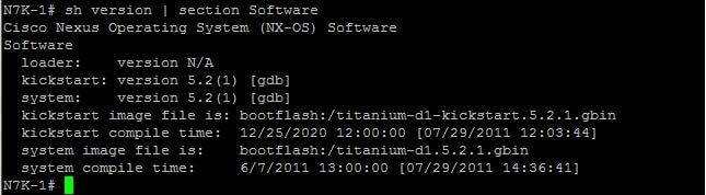
Originally, this exercise was performed on the Cisco Nexus 7000 (N7K) Titanium emulator, a tool that was instrumental for hands-on learning over a decade ago. While the foundational concepts of Virtual Routing and Forwarding (VRF) and Open Shortest Path First (OSPF) configuration on Cisco Nexus remain highly relevant, the network landscape, platforms, and operational methodologies have evolved significantly. This updated guide transitions the lab environment to modern alternatives like Cisco Modeling Labs (CML) 2.x or EVE-NG, and incorporates best practices relevant for the current-generation Cisco Nexus 9000 Series switches. We’ll cover not just the traditional CLI configuration but also introduce how network automation tools are used today.
For this lab, I’m emulating two Nexus switches (N7K-1 and N7K-2) to demonstrate VRF and OSPF interaction. Back when this guide was first written, I used VMware Workstation to host the Titanium N7K virtual machines. The original setup involved connecting virtual network adapters in VMware to emulate physical interfaces on the N7K.
The principle of mapping virtual interfaces (e.g., Eth2/1 on the Nexus) to underlying host network interfaces (e.g., Vmnet4 in VMware Workstation, or virtual bridges in CML/EVE-NG) is still crucial. I would confirm this mapping by toggling interface states and observing changes with show interface brief on the Nexus console.
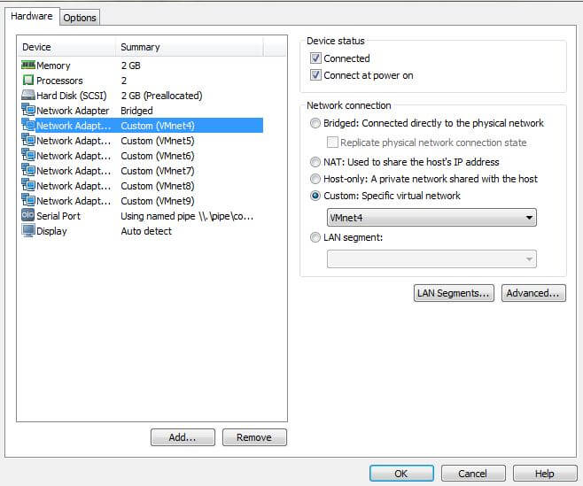
In our setup, Eth2/1 on both Nexus switches is logically connected via a shared virtual network (Vmnet4 in the original context, or a shared bridge in CML/EVE-NG). Ensuring they are on the same virtual segment is critical for them to establish connectivity. Now, let’s dive into the configuration.
Step 1: Initial Device Configuration – Hostnames and Interface IPs
First, I’ll assign hostnames to distinguish our two Nexus devices. This is a fundamental step for clarity in any network environment.
N7K# conf t
Enter configuration commands, one per line.  End with CNTL/Z.
N7K(config)# hostname N7K-1
I would repeat this for the second machine, assigning it the hostname N7K-2.
Next, I’ll assign IP addresses to the Eth2/1 interfaces on both Nexus switches and bring them up. This establishes the basic Layer 3 connectivity between our two devices.
# On N7K-1:
N7K-1(config)# interface Ethernet2/1
N7K-1(config-if)# ip address 12.12.12.1/24
N7K-1(config-if)# no shutdown

# On N7K-2:
N7K-2(config)# interface Ethernet2/1
N7K-2(config-if)# ip address 12.12.12.2/24
N7K-2(config-if)# no shutdown
After configuring the IP addresses, I’ll verify basic connectivity by pinging across the interfaces. This is a crucial first check.
N7K-1(config)# ping 12.12.12.2
PING 12.12.12.2 (12.12.12.2): 56 data bytes
64 bytes from 12.12.12.2: icmp_seq=0 ttl=254 time=1.747 ms
64 bytes from 12.12.12.2: icmp_seq=1 ttl=254 time=1.262 ms
64 bytes from 12.12.12.2: icmp_seq=2 ttl=254 time=1.423 ms
64 bytes from 12.12.12.2: icmp_seq=3 ttl=254 time=1.396 ms
64 bytes from 12.12.12.2: icmp_seq=4 ttl=254 time=1.58 ms

--- 12.12.12.2 ping statistics ---
5 packets transmitted, 5 packets received, 0.00% packet loss
round-trip min/avg/max = 1.262/1.481/1.747 ms
Step 2: Configuring VRF Instances and Interface Assignments
VRF (Virtual Routing and Forwarding) is a powerful technology that allows a single router or switch to host multiple independent routing tables. This is fundamental for network segmentation and multi-tenancy. By default, most interfaces on a Nexus device are assigned to the “default” VRF, except for the mgmt0 interface, which belongs to the “management” VRF for out-of-band access.
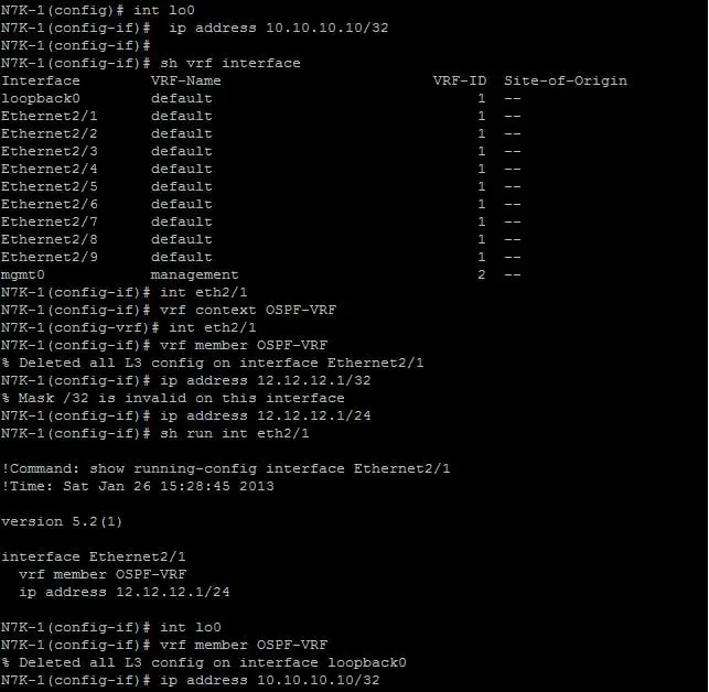
I’ll create a new VRF instance called OSPF-VRF. Then, I’ll create a Loopback0 interface on N7K-1 (10.10.10.10/32) and assign both Eth2/1 and Loopback0 to this new VRF. Loopback interfaces are often used as stable router IDs and for advertising internal networks within routing protocols.
# On N7K-1:
N7K-1(config)# vrf definition OSPF-VRF
N7K-1(config-vrf)# address-family ipv4 unicast
N7K-1(config-vrf-af)# exit
N7K-1(config-vrf)# exit

N7K-1(config)# interface Ethernet2/1
N7K-1(config-if)# vrf member OSPF-VRF
N7K-1(config-if)# ip address 12.12.12.1/24  # Re-apply IP after VRF assignment
N7K-1(config-if)# no shutdown

N7K-1(config)# interface Loopback0
N7K-1(config-if)# vrf member OSPF-VRF
N7K-1(config-if)# ip address 10.10.10.10/32
N7K-1(config-if)# no shutdown
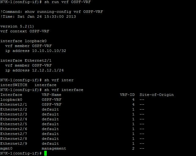
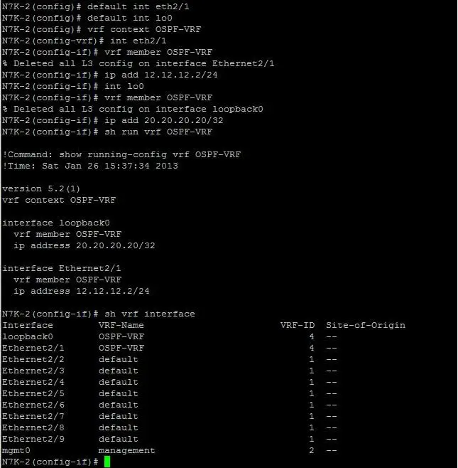
To verify the VRF assignments, I use the show vrf interface command. This confirms which interfaces are associated with OSPF-VRF.
I can also inspect the running configuration for the specific VRF to see its associated interfaces.
Now, I’ll apply the same VRF configuration on N7K-2, but with a different Loopback IP address (20.20.20.20/32).
# On N7K-2:
N7K-2(config)# vrf definition OSPF-VRF
N7K-2(config-vrf)# address-family ipv4 unicast
N7K-2(config-vrf-af)# exit
N7K-2(config-vrf)# exit

N7K-2(config)# interface Ethernet2/1
N7K-2(config-if)# vrf member OSPF-VRF
N7K-2(config-if)# ip address 12.12.12.2/24  # Re-apply IP after VRF assignment
N7K-2(config-if)# no shutdown

N7K-2(config)# interface Loopback0
N7K-2(config-if)# vrf member OSPF-VRF
N7K-2(config-if)# ip address 20.20.20.20/32
N7K-2(config-if)# no shutdown
Step 3: OSPF Configuration within the VRF
With our VRF instances and interface assignments complete, I’ll proceed with the OSPF configuration. This lab specifically runs OSPF within the OSPF-VRF context to demonstrate its functionality alongside VRFs. In NX-OS, similar to Cisco IOS, we first enable the OSPF feature globally and then configure the OSPF process within the VRF.
# Enable OSPF feature globally on both N7K-1 and N7K-2
N7K-1(config)# feature ospf

# On N7K-1:
N7K-1(config)# router ospf 1 vrf OSPF-VRF
N7K-1(config-router)# router-id 10.10.10.10
N7K-1(config-router)# interface Ethernet2/1
N7K-1(config-router-if)# ip ospf network point-to-point
N7K-1(config-router-if)# ip ospf area 0
N7K-1(config-router-if)# exit
N7K-1(config-router)# interface Loopback0
N7K-1(config-router-if)# ip ospf area 1
N7K-1(config-router-if)# exit

# On N7K-2:
N7K-2(config)# router ospf 1 vrf OSPF-VRF
N7K-2(config-router)# router-id 20.20.20.20
N7K-2(config-router)# interface Ethernet2/1
N7K-2(config-router-if)# ip ospf network point-to-point
N7K-2(config-router-if)# ip ospf area 0
N7K-2(config-router-if)# exit
N7K-2(config-router)# interface Loopback0
N7K-2(config-router-if)# ip ospf area 2
N7K-2(config-router-if)# exit
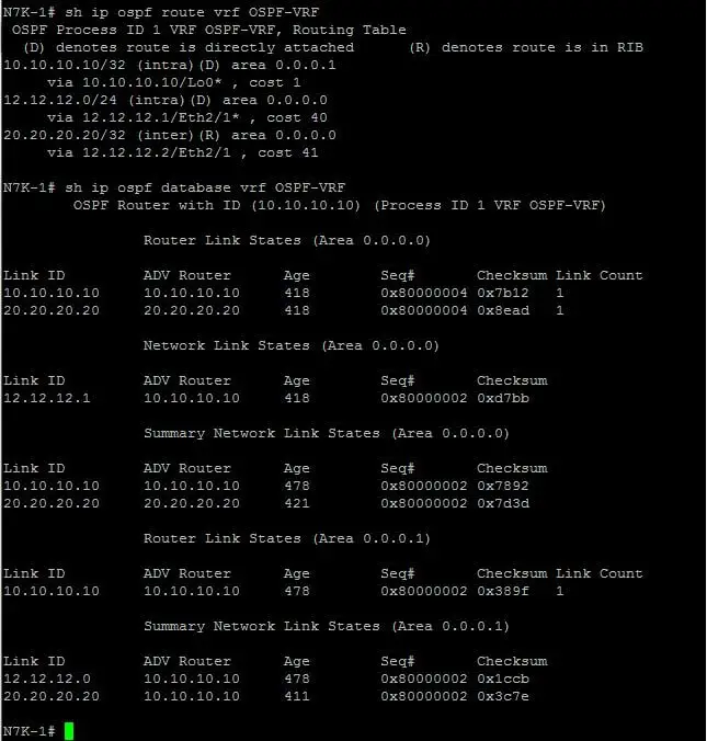
Here, Eth2/1 is assigned to OSPF Area 0 (the backbone area), while the Loopback0 interfaces are assigned to different areas (Area 1 on N7K-1 and Area 2 on N7K-2). This demonstrates a multi-area OSPF design within a VRF. Assigning the network type as point-to-point on Eth2/1 simplifies neighbor discovery and reduces overhead in a direct link scenario.
Step 4: Verification and Troubleshooting OSPF
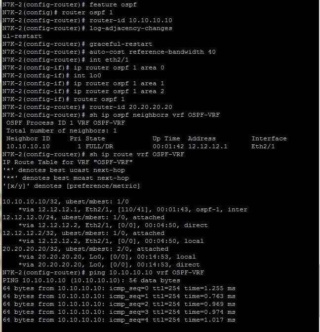
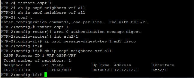
After configuring OSPF, the next critical step is to verify neighborship and route advertisements. I use various show commands, always remembering to specify the VRF context to see VRF-specific information.
# On N7K-1:
N7K-1# show ip ospf neighbor vrf OSPF-VRF
N7K-1# show ip route vrf OSPF-VRF
N7K-1# show ip ospf interface brief vrf OSPF-VRF
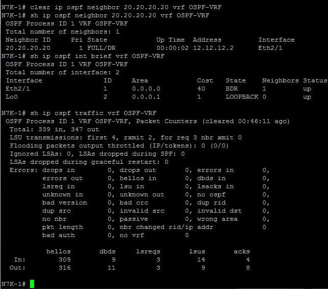
I can also clear the OSPF process to troubleshoot or force a re-convergence. For instance, to clear a specific neighbor relationship or restart the entire OSPF process within the VRF:
N7K-1# clear ip ospf neighbor 20.20.20.20 vrf OSPF-VRF
N7K-1# restart ospf 1 vrf OSPF-VRF
Monitoring OSPF traffic can provide insights into protocol operation, including hello packet exchanges and database synchronization.
N7K-1# show ip ospf traffic vrf OSPF-VRF
OSPF authentication is crucial for securing routing updates and preventing unauthorized routers from participating in the OSPF domain. While basic MD5 authentication has been common, modern deployments should prioritize stronger methods like SHA-256 via key chains for enhanced security. The configuration syntax is largely consistent between Cisco IOS and NX-OS.
# Example for OSPF authentication using MD5 (for legacy compatibility)
# On interface level for Eth2/1 within OSPF-VRF:
N7K-1(config-if)# ip ospf authentication message-digest
N7K-1(config-if)# ip ospf message-digest-key 1 md5 "MySecretKey"

# For modern deployments, prefer SHA-256 with key chains:
N7K-1(config)# key chain OSPF_AUTH_KEY
N7K-1(config-keychain)# key 1
N7K-1(config-keychain-key)# key-string "StrongSHA256Key"
N7K-1(config-keychain-key)# cryptographic-algorithm hmac-sha256
N7K-1(config-keychain-key)# exit
N7K-1(config-keychain)# exit

N7K-1(config)# interface Ethernet2/1
N7K-1(config-if)# ip ospf authentication key-chain OSPF_AUTH_KEY
Modernizing VRF and OSPF: From N7K to Nexus 9000 and Automation
While the core VRF and OSPF configurations demonstrated above remain valid, modern data center networks, particularly those built on the Cisco Nexus 9000 Series, leverage advanced capabilities and automation. Here’s a look at how these concepts are applied and extended today:
Cisco Nexus 7000 vs. Nexus 9000: A Platform Evolution
- Nexus 7000 Series: While still supported in many legacy environments, the N7K is largely superseded by the N9K for new deployments. N7K was known for its modularity and high performance in its era.
- Nexus 9000 Series: These platforms offer significantly higher density, lower power consumption, and support for 400G and beyond. Crucially, they are the foundation for Cisco Application Centric Infrastructure (ACI) and robust VXLAN EVPN fabrics, which have become the standard for modern data centers.
VRF and OSPF in Modern Data Centers: Beyond Basic Segmentation
The basic VRF setup is the starting point. In complex multi-tenant or hybrid cloud environments, we often see:
- BGP-based VRF Segmentation: Route Targets (RTs) are used with BGP EVPN to import and export VRF routes across a VXLAN overlay, enabling seamless multi-tenancy across the entire data center fabric.
- VRF Route Leaking: Controlled sharing of routes between different VRFs for specific service needs (e.g., shared services VRF), implemented with route-maps and BGP policies.
- OSPF vs. BGP EVPN: While OSPF is excellent for intra-area routing and smaller networks, BGP with EVPN is the dominant choice for scalable data center fabrics. It provides better control over route distribution, supports multi-tenancy natively through VXLAN, and integrates well with external networks and cloud environments. Understanding both is key for a modern network engineer.
Automation: From CLI to Infrastructure as Code (IaC)
Manually configuring devices via CLI, as shown in the original steps, introduces human error and doesn’t scale. Modern network operations rely heavily on automation:
- Ansible: Playbooks using the
cisco.nxoscollection can declaratively define VRF, OSPF, and interface configurations. This allows for idempotent, repeatable deployments. - Terraform: With the
cisco-nxosprovider, Terraform can manage the lifecycle of Nexus configurations as Infrastructure as Code, integrating network changes into a broader cloud or data center provisioning workflow. - NETCONF/YANG: Nexus switches support model-driven programmability using NETCONF and YANG data models (e.g., OpenConfig). This allows for programmatic configuration and telemetry streaming, moving away from screen-scraping CLI output.
Example: Ansible Playbook Snippet for VRF and OSPF
Here’s a conceptual Ansible playbook snippet that performs similar VRF and OSPF configurations:
---
- name: Configure Nexus VRF and OSPF
  hosts: nexus_switches
  gather_facts: false
  connection: network_cli

  tasks:
    - name: Configure VRF Definition
      cisco.nxos.nxos_vrf:
        name: OSPF-VRF
        state: present

    - name: Configure Loopback0 interface
      cisco.nxos.nxos_interfaces:
        config:
          - name: Loopback0
            description: "Loopback for OSPF-VRF"
            vrf: OSPF-VRF
            ipv4:
              address: "{{ (inventory_hostname == 'N7K-1') | ternary('10.10.10.10/32', '20.20.20.20/32') }}"
            state: present

    - name: Configure Ethernet2/1 interface for OSPF-VRF
      cisco.nxos.nxos_interfaces:
        config:
          - name: Ethernet2/1
            vrf: OSPF-VRF
            ipv4:
              address: "{{ (inventory_hostname == 'N7K-1') | ternary('12.12.12.1/24', '12.12.12.2/24') }}"
            state: present

    - name: Enable OSPF Feature
      cisco.nxos.nxos_feature:
        feature: ospf
        state: enabled

    - name: Configure OSPF Process within VRF
      cisco.nxos.nxos_ospf:
        ospf:
          1:
            vrf: OSPF-VRF
            router_id: "{{ (inventory_hostname == 'N7K-1') | ternary('10.10.10.10', '20.20.20.20') }}"
            interfaces:
              Ethernet2/1:
                area: 0
                network_type: point-to-point
              Loopback0:
                area: "{{ (inventory_hostname == 'N7K-1') | ternary('1', '2') }}"
      state: merged
vPC Integration with OSPF and VRF
In production Nexus environments, Virtual Port Channels (vPC) are ubiquitous for link and device redundancy. When combining vPC with OSPF and VRFs:
- vPC Peer Gateway: This feature is crucial when routing over a vPC, allowing the vPC peers to act as a single logical gateway for devices connected via the vPC.
- OSPF and vPC: OSPF adjacencies can form over vPC links. Careful design is needed, especially concerning Designated Router (DR) election and route advertisement, to ensure optimal traffic flow and fast convergence.
Model-Driven Telemetry and Observability
Instead of relying solely on manual show commands, modern networks use streaming telemetry (e.g., gNMI, pushing data to Kafka or analytics platforms). This provides real-time, granular visibility into OSPF neighbor states, VRF route changes, and interface statistics, enabling proactive monitoring and faster incident response.
Conclusion
This updated guide bridges the gap between foundational Cisco Nexus configuration concepts and the advanced methodologies employed in today’s data centers. While the original N7K and Titanium emulator provided an excellent learning platform for VRF and OSPF, the industry has shifted towards Nexus 9000 Series switches, BGP EVPN for scalability, and automation tools for efficiency and consistency.
As network engineers, embracing these modern tools and platforms, alongside a solid understanding of core routing principles, is essential for building and managing the complex, resilient networks of the future.

Can you shed some light?
Im running GNS3 Titanium and have the Nexus 7000 connected to an ASAv. The ASAv has sub interfaces with ip to form ospf adjacency with SVI on the Nexus. On the nexus side it’s running as a trunk and i see the hello packets from the ASAv on the wire but nothing making back from the nexus.
Feature ospf enabled
no passive interface on the svi connected to the ASav and nothing… what am i missing? is it a gns3 thing that i wont be able to accomplish this?
Hello
I need your help, I change all the MAC address and now I get the message
” serial1: Another process is already the server of the \\.\pipe\com_1
the device will be disconnected.
I need help on this, i will appreciate your reply.
I think you should try cisco VIRL now at (http://virl.cisco.com/).
i have configured 2 vms and able to access with com_1 and com_2 but unable to ping from n2k1 to n2k2 . could you please help me out to resolve the issue.
I installed Nexus Titanium VM in Vmware workstation.
I have another windows server 2008 r2 VM with Putty client.
When i use my putty client in windows 2008 VM to connect to Nexus Titanium over serial Port i get following error:
unable to open connection to \\.\pipe\com_1 unable to open serial port
Can you please help.
Hi guys,
In regards to your ping problem – if you deployed these 2 VMs from the same base image, VMWare may not have changed the MAC addresses of the NICs for you. It normally gives you an option on boot asking whether you Copied or Moved the VM. If you select Copied, it should change all the MACs for you. If you select “Moved”, it will leave them as the same.
From your Nexus devices, run a “Show interface eth2/1” and check that they both do not have the same Mac. If they do, you can manually change these via the VM Settings. It will be under the “Advanced” button of the Network Adapter. Alternatively you can edit the .vmx file directly.
Hope this helps!
Hi, I have the same problem. I used VMware work station to configure two instance of N7K starting from the same unzipped files copied to two different directories. Using CDP they see the each other but I can’t ping in any way in any vrf. Could be a problem of duplicated MAC address?
Thanks for any help
OK, I fixed it. It was a duplicated MAC addresses problem. I modified them in the VMnetx and it works, except than vrf management. Any idea?
can I use the same titanium 5.2 vmdk files for running 2 routers how to clone it. What I have done it is i made 2 folders and access using vm players so 2 vmplayers running the same vmdk files in 2 folder in order to create 2 routers. Let me install work station and see the same issue persists.
Let me thank you for the help, but it didnt answer my query. How can I make two nexus ping each other say n7k1 and n7k2 to communicate each other. Could you please guide me to solve this issue using virtual adapters, in your diagaram mentioned on top the first one i am not able to follow.
I have titanium vm files so i am using vm player to run so i started 2 vm player instance in order to run 2 routers it came up but both are having same management ip address. I cant communcate between 2 routers how to solve this. I need to ping between 2 routers. Can you guide me.
I will suggest you to use Vmware workstation instead of Vmplayer , in addition you also need putty to connect to the serial console. Below are the steps.
Configuring VMWARE Virtual Machine :-
Follow these steps to add a serial port to your VMWare Workstation virtual machine:
Attach the serial port to your VM. Open your VM settings dialog and click Add
Select Serial Port and click Next
Select Output to named pipe and in the box write “\\.\pipe\com_1” without quotes and click Next
Now you need to specify configuration for the named pipe. Make sure you select “This end is the server” and “The other end in an application” otherwise you won’t get any output from your console. Click Finish.
NOTE: The named pipe is created and deleted each time you power on, and power off your VM.
Configuring PuTTY Connection
When you launch PuTTY, you need to select Serial connection type, and then enter in the pipe name into the Serial Line text box:\\.\pipe\com_1
Once you connect, you’ll be able to configure your VM (be it Vyatta, or some other flavour) all via the VM’s serial interface.
Google internet you will find ways for sure. Let me know if this solves your query.
it is not communicating, i cant ping the two vm is comming up with titianium but i cant ping each other. Can you guide me how to connect two e2/1 of 2 titianium together
can you tell me how to connect the titanium to gns3..i am not able to console access the device. getting connection error in gns3..can you suggest.
Can you guide me how to interconnect 2 titianium running on two vm. I have 2 vm running on vmpalyer but it is not communicating each other can you guide me