- What is GLBP and Why do we use it?
- Benefits of Gateway Load Balancing Protocol
- Overview of Gateway Load Balancing Protocol
- Gateway Load Balancing Protocol MAC Address
- Gateway Load Balancing Protocol Preemption
- GLBP Load Balancing
- How to Configure GLBP
- Gateway Load Balancing Protocol Prerequisites
- GLBP Topology
- Useful commands for GLBP
- Troubleshooting GLBP
- Definitions and Acronyms used in the post
- Quiz
- Conclusion
- Further Reading
- Frequently Asked Questions about GLBP
What is GLBP and Why do we use it?
GLBP stands for Gateway Load Balancing Protocol and it is a Cisco proprietary First Hop Redundancy Protocol that attempts to overcome the limitations of existing redundant router protocols by adding basic load balancing functionality. In addition, it allows one virtual router to represent multiple physical routers on a network. It designates one virtual router as the AVG (Active Virtual Gateway), which is responsible for traffic forwarding and load balancing. The backup virtual routers are called AVFs (Active Virtual Forwarders) and act as a passive fail-over for the virtual gateway. If the AVG fails or becomes unreachable, the AVF takes over the virtual gateway role. It is also similar to HSRP. The only difference is the election process and the number of virtual routers.
If we use HSRP or VRRP, we may have one active router and the rest in the standby state. But with Gateway Load Balancing Protocol, we may have up to four active routers simultaneously; the rest of the routers are in the standby state.
You can also check another deep dive blog post about similarities and differences between VRRP, HSRP, and GLBP.
Watch this short video to get a quick understanding of the Gateway Load Balancing Protocol. If you are viewing on a big screen like a laptop or PC, click on the square box on the right side of the video to enlarge it on the screen. You do not need to do anything if you are watching on mobile.
Benefits of Gateway Load Balancing Protocol
- Load Sharing – You can configure Cisco GLBP so that several devices can share traffic from LAN clients, distributing the traffic load more evenly across available devices.
- Multiple Virtual Devices – On each device’s physical interface, Gateway Load Balancing Protocol allows up to 1024 virtual devices (GLBP groups) and four virtual forwarders per group.
- Preemption – The Gateway Load Balancing Protocol redundancy scheme enables you to replace an active virtual gateway (AVG) with a newly available backup virtual gateway with a higher priority.
- Authentication – Gateway Load Balancing Protocol utilizes the industry-standard message digest 5 (MD5) algorithm to boost reliability, security, and protection against software that attempts to spoof the GLBP protocol.
Overview of Gateway Load Balancing Protocol
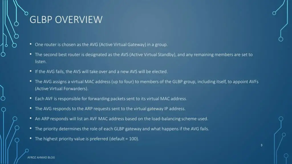
In addition to setting priorities on different gateway routers, Gateway Load Balancing Protocol allows a weighting parameter to be set. Routers will respond to ARP requests with MAC addresses pointing to different routers based on their weighting (in comparison to others in the same virtual router group). Although load balancing is performed based on the number of hosts that will utilize each gateway router, rather than on the volume of traffic. By default, it does round-robin load balancing.
Gateway Load Balancing Protocol elects each group an AVG (Active Virtual Gateway). Other group members serve as a backup in the event that AVG fails. If more than two members are present, the second-best AVG is placed in the Standby state, while the remaining members are in the Listening state. This is monitored using hello and hold timers, which are set to three and ten seconds, respectively. After that, the elected AVG issues a virtual MAC address to each member of the GLBP group, including itself, enabling AVFs (Active Virtual Forwarders). Each AVF is in charge of forwarding packets addressed to its virtual MAC address. Thus, up to four AVFs may be operational concurrently.
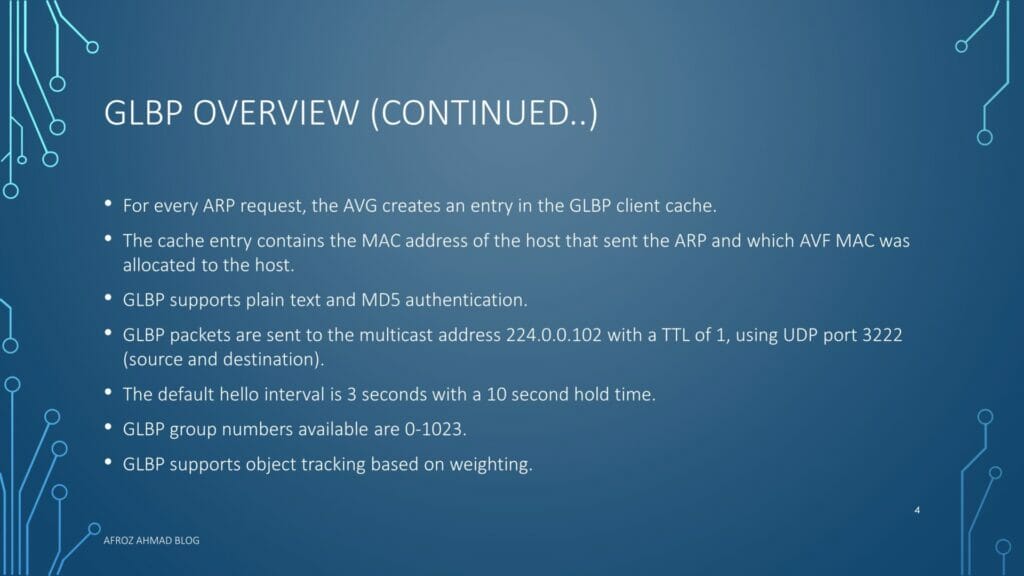
By default, Gateway Load Balancing Protocol routers transmit hello packets to their neighbors every three seconds over UDP 3222 using the local GLBP multicast address 224.0.0.102. (source and destination).
Gateway Load Balancing Protocol MAC Address
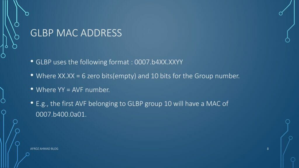
- Gateway Load Balancing Protocol uses the following format for GLBP virtual mac address: 0007.b4XX.XXYY
- Where XX.XX = 6 zero bits(empty) and 10 bits for the Group number.
- Where YY = AVF number. •E.g., the first AVF belonging to GLBP group 10 will have a MAC of 0007.b400.0a01.
Gateway Load Balancing Protocol Preemption
- Gateway Load Balancing Protocol Preemption enables the router with the higher priority to immediately become the AVG or an AVF.
- By default preemption is not enabled for the AVG. This must be enabled manually.
- By default, preemption is enabled for the AVFs. That may be disabled.
GLBP Load Balancing
- Gateway Load Balancing Protocol support three different load-sharing schemes.
- Round-Robin
- The AVF MAC addresses are used sequentially in the ARP replies to the virtual gateway IP address with round-robin.
- This is the default load-balancing scheme.
- Host-Dependent
- The source MAC of a host is used to determine which AVF MAC the host is directed towards.
- One host will always use the same AVF MAC as long as number AVFs in the GLBP group are constant.
- Weighted
- Each AVF will be assigned a weight and this weight will be advertised to the AVG.
- The AVG will respond with the AVF MAC in proportion to the weight balance.
- Round-Robin
How to Configure GLBP
- Enabling and Verifying Gateway Load Balancing Protocol – Each gateway in a GLBP group must have the same group number specified. Additionally, the virtual IP address must be configured on at least one gateway in the GLBP group.
- If you enable a GLBP group first before personalizing it, the device may seize control of the group and become the AVG before customization. Therefore, if you intend to configure Gateway Load Balancing Protocol, you should do so prior to enabling it.
- How to configure GLBP
- enable
- configure terminal
- interface type number ip address ip-address mask [secondary ] –> Specifies an interface’s primary or secondary IP address.
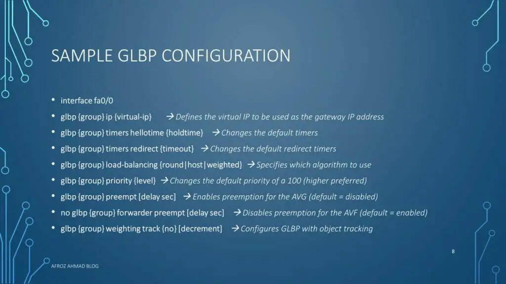
- glbp group ip [ip-address [secondary ] –> Defines the virtual IP to be used as the gateway IP address
- glbp group ip [ip-address [secondary ] –> After identifying a primary IP address, you may use the glbp group ip command again with the secondary keyword to indicate that this group supports additional IP addresses.
- glbp group timers [msec ] hellotime [msec ] holdtime –> Changes the default timers
- glbp group timers redirect redirect timeout –> Changes the default redirect timers
- glbp group load-balancing [host-dependent | round-robin | weighted ] –> Specifies which algorithm to use
- glbp group priority level –> Changes the default priority of a 100 (higher preferred)
- glbp group preempt [delay minimum seconds] –> Enables preemption for the AVG (default = disabled)
- no glbp {group} forwarder preempt [delay sec] –> Disables preemption for the AVF (default = enabled)
- glbp group weighting track {no} [decrement] –> Configures GLBP with object tracking
- glbp group client-cache maximum number [timeout minutes] –> (Optional) Enables the GLBP client cache.
- show glbp [interface-type interface-number] [group] [state] [brief ] –> Verify GLBP
Gateway Load Balancing Protocol Prerequisites
Before configuring Gateway Load Balancing Protocol, we should verify that the devices on the physical interfaces can handle multiple MAC addresses. Please keep in mind that each GLBP forwarder requires an additional MAC address to be configured.
GLBP Topology

Let’s now start with our topology. Here PC1, PC2, PC3, and PC4 routing is disabled with “no ip routing,” and all are pointing towards the GLBP assigned address 10.0.0.254, which is assigned on the LAN interface R1 Let’s now start with our topology. Here PC1, PC2, PC3, and PC4 routing is disabled with “no ip routing,” All are pointing towards the GLBP assigned address 10.0.0.254, which is assigned on the LAN interface R1 and R2 pointing towards end hosts. Additionally, R1(AS-12) is connected to ISP1(AS-501), and R2(AS-12) is connected to ISP2(502). I have not configured R1 and R2 as an IBGP neighbor, although R1 and R2 receive the same routes from ISP1 and ISP2.
Pre-configurations of all devices.
PC1, PC2, PC3, and PC4 have addresses in range 10.0.0.0/24, and ip routing is disabled, and the default gateway is configured to be 10.0.0.254(GLBP address) assigned on the Fastethernet0/0 interface of R1 and R2.
Sample config of PC1
PC1#show run int fa0/0
interface FastEthernet0/0
ip address 10.0.0.1 255.255.255.0
end
PC1#show run | i default
ip default-gateway 10.0.0.254
PC1#show ip route
Default gateway is 10.0.0.254
Host Gateway Last Use Total Uses Interface
ICMP redirect cache is empty
R1
R1#show run int fa0/0
interface FastEthernet0/0
ip address 10.0.0.101 255.255.255.0
glbp 1 ip 10.0.0.254
R1#show run int S0/0
interface Serial0/0
ip address 11.11.11.1 255.255.255.0
R1#show run | s bgp
router bgp 12
no synchronization
bgp log-neighbor-changes
neighbor 11.11.11.254 remote-as 501
no auto-summary
R1#show ip bgp summary | b Nei
Neighbor V AS MsgRcvd MsgSent TblVer InQ OutQ Up/Down State/PfxRcd
11.11.11.254 4 501 35 31 5 0 0 00:28:31 4
R1#sh ip bgp | b Network
Network Next Hop Metric LocPrf Weight Path
*> 33.33.33.1/32 11.11.11.254 0 0 501 i
*> 33.33.33.2/32 11.11.11.254 0 0 501 i
*> 33.33.33.3/32 11.11.11.254 0 0 501 i
*> 33.33.33.4/32 11.11.11.254 0 0 501 i
R2
R2#show run int fa0/0
interface FastEthernet0/0
ip address 10.0.0.102 255.255.255.0
glbp 1 ip 10.0.0.254
R2#sh run int s0/0
interface Serial0/0
ip address 22.22.22.2 255.255.255.0
R2#show run | s bgp
router bgp 12
no synchronization
bgp log-neighbor-changes
neighbor 22.22.22.254 remote-as 502
no auto-summary
R2#show ip bgp summary | b Neighbor
Neighbor V AS MsgRcvd MsgSent TblVer InQ OutQ Up/Down State/PfxRcd
22.22.22.254 4 502 38 34 5 0 0 00:31:42 4
R2#show ip bgp | b Network
Network Next Hop Metric LocPrf Weight Path
*> 33.33.33.1/32 22.22.22.254 0 0 502 i
*> 33.33.33.2/32 22.22.22.254 0 0 502 i
*> 33.33.33.3/32 22.22.22.254 0 0 502 i
*> 33.33.33.4/32 22.22.22.254 0 0 502 i
ISP1
ISP1#show run int s0/0
interface Serial0/0
ip address 11.11.11.254 255.255.255.0
ISP1#show run | s bgp
router bgp 501
no synchronization
bgp log-neighbor-changes
network 33.33.33.1 mask 255.255.255.255
network 33.33.33.2 mask 255.255.255.255
network 33.33.33.3 mask 255.255.255.255
network 33.33.33.4 mask 255.255.255.255
neighbor 11.11.11.1 remote-as 12
no auto-summary
ISP1#show run | i ip route
ip route 0.0.0.0 0.0.0.0 11.11.11.1
ISP2
ISP2#show run int s0/0
interface Serial0/0
ip address 22.22.22.254 255.255.255.0
ISP2#show run | s bgp
router bgp 502
no synchronization
bgp log-neighbor-changes
network 33.33.33.1 mask 255.255.255.255
network 33.33.33.2 mask 255.255.255.255
network 33.33.33.3 mask 255.255.255.255
network 33.33.33.4 mask 255.255.255.255
neighbor 22.22.22.2 remote-as 12
no auto-summary
ISP2#show run | i ip route
ip route 0.0.0.0 0.0.0.0 22.22.22.2
Now, let’s start with the verifications of GLBP. As we have not configured any fancy kinds of stuff so far in GLBP, let us check the output of “show glbp” on R1 and R2, respectively.
R1#show glbp
FastEthernet0/0 – Group 1
State is Standby —>>This is standby AVG as this has the lower ip address assigned similar to HSRP or VRRP.
1 state change, last state change 00:29:49
Virtual IP address is 10.0.0.254
Hello time 3 sec, hold time 10 sec
Next hello sent in 1.772 secs
Redirect time 600 sec, forwarder timeout 14400 sec
Preemption disabled —>> Similar to HSRP, Preemption is disabled by default, unlike VRRP, which has preemption enabled by default.
Active is 10.0.0.102, priority 100 (expires in 7.136 sec) –>>This is pointing towards the Active Gateway that is R2.
Standby is local —>>R1 is standby AVG.
Priority 100 (default) —>>Default priority.
Weighting 100 (default 100), thresholds: lower 1, upper 100
Load balancing: round-robin
Group members:
c200.1550.0000 (10.0.0.101) local —>>AVF’s and there respective MAC addresses.(R1)
c201.1550.0000 (10.0.0.102) —>>AVF’s and there respective MAC addresses.(R2)
There are 2 forwarders (1 active)
Forwarder 1
State is Listen
MAC address is 0007.b400.0101 (learnt)
Owner ID is c201.1550.0000 –>>AVF is R1; this is in the “listen” state, answering the next ARP response.
Time to live: 14397.124 sec (maximum 14400 sec)
Preemption enabled, min delay 30 sec
Active is 10.0.0.102 (primary), weighting 100 (expires in 8.780 sec)
Forwarder 2
State is Active
1 state change, last state change 00:29:58
MAC address is 0007.b400.0102 (default)
Owner ID is c200.1550.0000 —>>AVF is R2, and this is Active means this will answer the ARP.
Preemption enabled, min delay 30 sec
Active is local, weighting 100
R2#show glbp
FastEthernet0/0 – Group 1
State is Active —>>This is AVG as this has the higher ip address assigned similar to HSRP or VRRP.
2 state changes, last state change 00:30:42
Virtual IP address is 10.0.0.254
Hello time 3 sec, hold time 10 sec
Next hello sent in 0.372 secs
Redirect time 600 sec, forwarder timeout 14400 sec
Preemption disabled —>>Similar to HSRP, Preemption is disabled by default, unlike VRRP, which has preemption enabled by default.
Active is local —>> This indicated that this is AVG for this group.
Standby is 10.0.0.101, priority 100 (expires in 9.024 sec)
Priority 100 (default) —>>Priority of all FHRP’s by default is 100.
Weighting 100 (default 100), thresholds: lower 1, upper 100 —>>Default config of GLBP.
Load balancing: round-robin —>>Default load-balancing of GLBP.
Group members:
c200.1550.0000 (10.0.0.101) —>>AVF’s and there respective MAC addresses.(R1)
c201.1550.0000 (10.0.0.102) local —>>AVF’s and there respective MAC addresses.(R2)
There are 2 forwarders (1 active)
Forwarder 1
State is Active
1 state change, last state change 00:30:32
MAC address is 0007.b400.0101 (default)
Owner ID is c201.1550.0000 —>>AVF is R2, and this is Active means this will answer the ARP.
Redirection enabled
Preemption enabled, min delay 30 sec
Active is local, weighting 100
Client selection count: 2
Forwarder 2
State is Listen
MAC address is 0007.b400.0102 (learnt)
Owner ID is c200.1550.0000 —>>AVF is R1; this is in the “listen” state, answering the next ARP response.
Redirection enabled, 597.904 sec remaining (maximum 600 sec)
Time to live: 14397.904 sec (maximum 14400 sec)
Preemption enabled, min delay 30 sec
Active is 10.0.0.101 (primary), weighting 100 (expires in 7.900 sec)
Client selection count: 2
So far, so good, so we are doing some Load balancing out here, but really are we doing? How can we check. The easy way to check is from pinging from host PC1 through PC4 and see do we are actually distributing the load, as seen in the above output.
Let us start.
Pc1
PC1#ping 33.33.33.1
Type escape sequence to abort.
Sending 5, 100-byte ICMP Echos to 33.33.33.1, timeout is 2 seconds:
!!!!!
Success rate is 100 percent (5/5), round-trip min/avg/max = 1/241/1080 ms
PC1#show arp | i 10.0.0.254
Protocol Address Age (min) Hardware Addr Type Interface
Internet 10.0.0.254 0 0007.b400.0101 ARPA FastEthernet0/0 —>>AVF is R2.
PC2
PC2#ping 33.33.33.2
Type escape sequence to abort.
Sending 5, 100-byte ICMP Echos to 33.33.33.2, timeout is 2 seconds:
!!!!!
Success rate is 100 percent (5/5), round-trip min/avg/max = 24/241/1064 ms
PC2#show arp | i 10.0.0.254
Protocol Address Age (min) Hardware Addr Type Interface
Internet 10.0.0.254 0 0007.b400.0102 ARPA FastEthernet0/0 —>>AVF is R1.
PC3
PC3#ping 33.33.33.3
Type escape sequence to abort.
Sending 5, 100-byte ICMP Echos to 33.33.33.3, timeout is 2 seconds:
!!!!!
Success rate is 100 percent (5/5), round-trip min/avg/max = 12/231/1060 ms
PC3#sh arp | i 10.0.0.254
Protocol Address Age (min) Hardware Addr Type Interface
Internet 10.0.0.254 0 0007.b400.0101 ARPA FastEthernet0/0 —>>AVF is R2.
PC4
PC4#ping 33.33.33.4
Type escape sequence to abort.
Sending 5, 100-byte ICMP Echos to 33.33.33.4, timeout is 2 seconds:
!!!!!
Success rate is 100 percent (5/5), round-trip min/avg/max = 12/233/1056 ms
PC4#show arp | i 10.0.0.254
Protocol Address Age (min) Hardware Addr Type Interface
Internet 10.0.0.254 0 0007.b400.0102 ARPA FastEthernet0/0 —>>AVF is R1.
So the output is quite promising; we have sent twenty packets towards our destinations, and 10 packets are routed via R1, and 10 packets are routed via R2. As the default Load Balancing in GLBP is round-robin, as we have seen in the output of “show glbp,” the forwarding engine inside the GLBP will serve packets one after another in a round-robin fashion. As evident from the output.
Now let’s modify some of the outputs, here our connections to ISP1 and ISP2 are both T1 means (BW 1544 Kbit), now let’s say the connection to ISP1 from R1 is DS3 channel(45 Mbps), and now we want packets are more likely to be forwarded towards R1 in comparison to R2. So let us modify the weighting and see the results.
To actually test the load-balancing, we need to create an extended access list on R1 and R2 that we can use for packet counters and ping from our end hosts PC1 through PC4. To change configurations on R1 accordingly as this is the faster link, I have increased the weighting of R1 as double than R2 and decreased the Forwarder preempt delay from Default 30 seconds to 1 second on R1.So the final config on R1 is.
R1
R1#show run int fa0/0
interface FastEthernet0/0
ip address 10.0.0.101 255.255.255.0
ip access-group 100 in
duplex auto
speed auto
glbp 1 ip 10.0.0.254
glbp 1 weighting 210 lower 195 upper 205 —>>This side weighting is twice R1(100 default).
glbp 1 load-balancing weighted —>>This will change the default LB from Round-Robin to Weighted.
glbp 1 forwarder preempt delay minimum 1 —>>The forwarder preemption delay is minimum to 1 sec.
end
R2
R2#show run int fa0/0
interface FastEthernet0/0
ip address 10.0.0.102 255.255.255.0
ip access-group 100 in
duplex auto
speed auto
glbp 1 ip 10.0.0.254
glbp 1 load-balancing weighted —>>This will change the default LB from Round-Robin to Weighted.
glbp 1 forwarder preempt delay minimum 1 —>>The forwarder preemption delay is minimum to 1 sec.
end
The access-list 100 is used as a packet counter and applied inbound on R1 and R2; the config is below.
access-list 100 permit icmp any any echo
access-list 100 permit ip any any
access-list 100 deny ip any any log
Now, let’s start pinging from PC1 through PC4 with a repeat count of 1000 each.
PC1#ping 33.33.33.1 re 1000
PC2#ping 33.33.33.2 re 1000
PC3#ping 33.33.33.3 re 1000
PC4#ping 33.33.33.4 re 1000
Now let’s see the R1 and R2 using the access list we have made for packet counters.
R1#show access-list
Extended IP access list 100
10 permit icmp any any echo (3000 matches)
20 permit ip any any (195 matches)
30 deny ip any any log
R2#show access-list
Extended IP access list 100
10 permit icmp any any echo (1000 matches)
20 permit ip any any (189 matches)
30 deny ip any any log
Voila, the results are quite good as we can see 4000 packets sent out, of which R1 and 1000 packets towards R2 forward 3000 packets. But, unfortunately, it is tough to simulate actual load-balancing in GLBP. If we can refer to Cisco DOC-CD GLBP, the load balancing algorithm is not well documented here.
We can configure authentication and tracking, same as we use in HSRP and VRRP, the configurations are almost the same; we need to replace keyword glbp in GLBP by standby in HSRP or vrrp in VRRP; the rest are the same.
Useful commands for GLBP
- Show glbp –> Show the GLBP statistics, priority, counters, etc.
- Show interface brief –> lists the interfaces and displays the basic IP configuration of each
- Debug glbp –> Shows all GLBP errors, events, packets and state transitions
Troubleshooting GLBP
In order to display diagnostic output related to specific GLBP operating events, you should always start with the “debug glbp” command and add debug condition glbp, debug glbp errors, debug glbp events, debug glbp packets, and debug glbp terse commands if necessary. Please note that these commands produce a large volume of outputs which can degrade the running device performance.
Definitions and Acronyms used in the post
- GLBP : Gateway Load Balancing Protocol
- VRRP : Virtual Router Redundancy Protocol
- FHRP: First Hop Redundancy Protocol
- AVG : Active Virtual Gateway
- AVS : Active Virtual Standby
- AVFs : Active Virtual Forwarders
- ARP: Address Resolution Protocol
Quiz
Conclusion
In this post, we looked into GLBP, which provides gateway redundancy and load balancing features. We further enhanced and tested our configuration by changing the load balancing algorithm from round-robin (default) to weighted.
If you liked this post, please share it to reach out to other people who might be searching for the same topic.
Further Reading
HSRP config explained in detail with video, diagrams, and configs.
Good resources to look for GLBP.
INE BLOG:- GLBP Explained
Cisco Site apart from DOC-Cd:- GLBP
Frequently Asked Questions about GLBP
How does cisco GLBP work ?
GLBP stands for Gateway Load Balancing Protocol and it is a Cisco proprietary First Hop Redundancy Protocol that attempts to overcome the limitations of existing redundant router protocols by adding basic load balancing functionality. In addition, it allows one virtual router to represent multiple physical routers. It designates one virtual router as the AVG (Active Virtual Gateway), which is responsible for traffic forwarding and load balancing. The backup virtual routers are called AVFs (Active Virtual Forwarders) and act as a passive fail-over for the virtual gateway. If the AVG fails or becomes unreachable, the AVF takes over the virtual gateway role. It is also similar to HSRP. The only difference is the election process and the number of virtual routers.
How glbp load balancing works?
- Gateway Load Balancing Protocol support three different load-sharing schemes.
- Round-Robin
- The AVF MAC addresses are used sequentially in the ARP replies to the virtual gateway IP address with round-robin.
- This is the default load-balancing scheme.
- Host-Dependent
- The source MAC of a host is used to determine which AVF MAC the host is directed towards.
- One host will always use the same AVF MAC as long as number AVFs in the GLBP group are constant.
- Weighted
- Each AVF will be assigned a weight and this weight will be advertised to the AVG.
- The AVG will respond with the AVF MAC in proportion to the weight balance.
- Round-Robin
What is GLBP used for?
GLBP is used to provide Gateway redundancy along with basic load balancing functionality in LAN environments.
What is HSRP VRRP and GLBP?
HSRP, VRRP, and GLBP are First Hop redundancy Protocols and thus provide Gateway redundancy in LAN environments. HSRP stands for Hot Standby Protocol, VRRP stands for Virtual Router Redundancy Protocol and GLBP stands for Gateway Load Balancing Protocol. HSRP and GLBP are Cisco Proprietary while VRRP is industry standard.
How do I configure GLBP?
- Follow these steps to configure GLBP on an Interface
- enable
- configure terminal
- interface type number ip address ip-address mask [secondary ] –> Specifies an interface’s primary or secondary IP address.
- glbp group ip [ip-address [secondary ] –> Defines the virtual IP to be used as the gateway IP address
- glbp group ip [ip-address [secondary ] –> After identifying a primary IP address, you may use the glbp group ip command again with the secondary keyword to indicate that this group supports additional IP addresses.
- glbp group timers [msec ] hellotime [msec ] holdtime –> Changes the default timers
- glbp group timers redirect redirect timeout –> Changes the default redirect timers
- glbp group load-balancing [host-dependent | round-robin | weighted ] –> Specifies which algorithm to use
- glbp group priority level –> Changes the default priority of a 100 (higher preferred)
- glbp group preempt [delay minimum seconds] –> Enables preemption for the AVG (default = disabled)
- no glbp {group} forwarder preempt [delay sec] –> Disables preemption for the AVF (default = enabled)
- glbp group weighting track {no} [decrement] –> Configures GLBP with object tracking
- glbp group client-cache maximum number [timeout minutes] –> (Optional) Enables the GLBP client cache.
- show glbp [interface-type interface-number] [group] [state] [brief ] –> Verify GLBP
- Epson EpiqVision Flex CO-W01 Projector Review - February 21, 2025
- How to Log in to Your Netgear Router - January 17, 2025
- Gaimoo GM200 Mini Projector Review - January 12, 2025