- What is MSTP(Multiple Spanning Tree Protocol)?
- What does MSTP stand for?
- What is MSTP or Multiple Spanning Tree Protocol?
- What are the Benefits of using MSTP?
- What are some of the drawbacks of using MSTP?
- Multiple Spanning Tree Instance Ports
- What are MST Regions?
- How many Instance types are in Multiple Spanning Tree Protocol?
- What is IST in Multiple Spanning Tree Protocol?
- What are MSTIs or Multiple Spanning Tree Instances?
- Explain MSTP BPDUs
- MSTP hierarchy explained
- What is CST (Common Spanning-Tree)?
- What is CIST (Common and Internal Spanning-Tree)?
- CIST Regional Root
- What is CIST Root?
- What is CIST Internal Root Path Cost?
- What is CIST External Root Path Cost?
- What is Boundary Bridge in MSTP?
- What is Internal Bridge in MSTP?
- MSTP Configuration on Cisco Devices
- Conclusion
- Frequently Asked Questions:-
What is MSTP(Multiple Spanning Tree Protocol)?
Multiple Spanning Tree Protocol (MSTP) is an IEEE standard that allows a single physical network switch to support multiple spanning-tree instances. The MSTP standard is useful for companies with lots of VLANs in the network and wants separate spanning-tree instances for groups of VLANs. This blog post will discuss What is MSTP or Multiple Spanning Tree Protocol, its core components, its real benefits and drawbacks, configuration, and best practices.
I would highly recommend you to read about Spanning Tree Protocol, Rapid Spanning Tree Protocol, VLANs, VLAN tagged vs untagged, and VLAN Trunking Protocol topics to grasp the basic understanding of Spanning Tree Protocol related terms before moving forward in this article. Let us get started.
What does MSTP stand for?
MSTP stands for Multiple Spanning Tree Protocol.
What is MSTP or Multiple Spanning Tree Protocol?
Cisco’s proprietary PVSTP (per Vlan STP) or MISTP (Multiple Instances STP) was the inspiration for the IEEE 802.1S-2002 standard known as MSTP (Multiple Spanning Tree Protocol).
To allow instances to be VLAN-independent, MSTP decouples the VLAN from the spanning-tree instance relationship. It is necessary to create the instances administratively because each instance will have multiple VLANs assigned to it. Each instance is in charge of its own Spanning-Tree Algorithm (STA).
The underlying protocol operation was made possible by incorporating RSTP (802.1W) functions into MSTP. When using MSTP, it is critical to ensure that all point-to-point links are operating in full-duplex mode to facilitate rapid transitioning. Therefore, when using MSTP, the sys-id-ext is the same as the instance number.
In short, MSTP combines the benefits of RSTP and supports multiple instances of Spanning Tree Protocol.
What are the Benefits of using MSTP?
MSTP has several benefits compared to other STP variants. For example,
Using MSTP, you can create multiple spanning-tree instances that are completely separate from one another, and each of which can take a different path (if available physically in the network) to reach the same destination. This provides fault tolerance as well as improved network performance for the user.
MSTP is fast by nature as it incorporates RSTP as the underlying protocol.
The vast majority of switch vendors support the Multiple Spanning Tree Protocol (MSTP).
What are some of the drawbacks of using MSTP?
While MSTP is a beneficial protocol, it does have some disadvantages that you should be aware of before using it on your network devices.
One potential drawback of using MSTP is that it can be more complicated to configure and manage than other spanning tree protocols.
Also, as you study MSTP, remember that knowledge of STP and RSTP is essential to understanding MSTP.
Additionally, If you use MSTIs (Multiple Spanning Tree Instances) and do not put all VLANs on the IST, any changes, such as adding a new VLAN to the MSTI, will cause the CIST to reconnect.
As per my experience, MSTP has the potential to form a loop when connecting with the networks which are running other variants of STP (STP, PVSTP+, PVRSTP+, etc.). Therefore, always test the design in the lab properly before implementing MSTP in production.

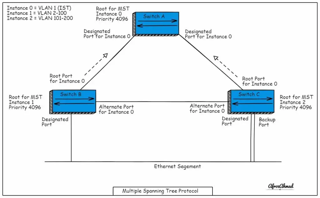
Multiple Spanning Tree Instance Ports
MSTP port types are similar to RSTP but on a per-instance basis.
Root: Root port connects the Bridge to the MSTI Regional Root at the lowest possible cost.
Designated: Provides the shortest route from the connected LANs to the Regional Root via the Bridge.
Master: A master port connects an MSTP region to an outlying CIST root.
Alternate: The port provides a second path to the root device from the root interface, in case the first path fails.
Backup: The port serves as a fallback path to the designated port path leading to the Spanning Tree leaves when the primary path is unavailable. Backup ports occur when two ports are connected in a loop by a point-to-point link, resulting in the creation of a backup port. Backup ports can also occur when a LAN has two or more connections that are connected to the same shared segment as the primary connection.
What are MST Regions?
An MST region is a group of switches with the same configuration attributes and managed by a single entity.
An MST configuration attributes consist of:
- A 32 bytes Configuration name.
- A 2 bytes Revision number.
- A Mapping table to map VLANs to instance numbers.
For two switches to belong to the same region, all the above configuration attributes must be the same.
If any one of the above configuration attributes differs or is missing, then this means that two bridges are in different regions.
How many Instance types are in Multiple Spanning Tree Protocol?
In an MSTP based network, the following instance and regions types can exist:
- Each region has its own IST (Internal Spanning-Tree).
- A region containing one or more Instances of Multiple Spanning Trees (MSTI).
- Each network has a single CST (Common Spanning-Tree).
- Only one Common and Internal Spanning-Tree or CIST for all MST regions.
What is IST in Multiple Spanning Tree Protocol?
IST is MST Instance 0, and it is like a control plane for MST. It is the RSTP instance running in an MST region, and it is in charge of setting up a loop-free topology. Instance 0 is always active on all links within an MST region, and by default, all VLANs are mapped to instance 0
IST is the only MST instance in a region that can send and receive BPDUs. Instance 0 selects a root bridge known as the IST root using the lowest bridge ID. Additionally, only the IST can set the STP hello, forward delay, and max-age timers.
Please note:- It is best practice not to assign user/data VLANs to IST or instance 0.
What are MSTIs or Multiple Spanning Tree Instances?
MSTIs or Multiple Spanning Tree Instances are additional RSTP instances that are manually enabled and used by a group of VLANs that share the same logical topology. Each MSTI has its own set of Spanning tree Algorithms, such as the root bridge and root path cost. MSTIs never interact with switches outside of their region.
Moreover, MSTI topologies are derived from the IST topology. Therefore, all MSTIs in the same region use the same protocol timers inherited from the IST.
Explain MSTP BPDUs
Multiple Spanning Tree BPDUs utilize protocol version 3, and they contain configuration name, revision number, and digest of the VLAN instance mapping table. Every switch generates one configuration BPDU every Hello interval (default = 2 seconds), similar to RSTP.
The standard RSTP BPDU format is used to convey all MSTP information. In addition, MST BPDUs contain the IST information and one MRecord for each active MSTI.
What are MRecords?
Each MRecord contains information about the root bridge and sender bridge for that particular instance. MRecords are local to a region, which is why MSTI changes in one region do not affect MSTIs in another region.
On the other hand, Topology Changes (TCs) are propagated to all pseudo-bridges (local bridge for CST), CIST changes affect every pseudo-bridge and its MSTIs.
Remember that the spanning-tree topology view will be the same for all VLANs assigned to an MSTI. Therefore, you should be extra cautious when removing selected VLANs from inter-switch trunks from the same instance.
MSTP hierarchy explained
When connecting multiple MST regions or different modes of STP, MSTP employs a spanning-tree hierarchy. The top level of the hierarchy is CST/CIST, and the lowest level of the hierarchy is IST.
What is CST (Common Spanning-Tree)?
The CST or Common Spanning Tree interconnects the MST regions and any other 802.1D or 802.1w instance in a network. For the entire bridged network, the CST generates a single spanning-tree instance.
One logical bridge, also known as a pseudo-bridge, is visible to CST in an MST region. For STA calculations, pseudo-bridges are represented by the details of the CIST root or the CIST regional root.
What is CIST (Common and Internal Spanning-Tree)?
A CIST is a grouping of ISTs from each MST region that forms an inter-region spanning-tree instance.
CIST Regional Root
CIST Regional Root is the boundary bridge chosen for each region with the lowest CIST external root path cost. Therefore, the elected CIST regional root also becomes the region’s IST root.
A regional root selects one boundary port as the CST root port (also known as the master port) and blocks all other boundary ports. The role is surrendered if a regional root receives a lower CIST external root path cost on an internal link. If the network has only one region, the CIST regional root is also elected as the CIST root.
What is CIST Root?
The CIST root is the bridge with the smallest Bridge ID across all regions. It could be either a boundary or an internal bridge. All boundary ports are unblocked and in the CIST designated-forwarding state of a region containing the CIST root bridge.
What is CIST Internal Root Path Cost?
The CIST internal root path cost is the cost of the intra-region link used to reach the CIST Regional Root.
What is CIST External Root Path Cost?
The cost of the inter-region links used to reach the CIST Root is called the CIST external root path cost. This external root path cost does not include CIST internal root path costs. External root path cost BPDUs will be transparently relayed on internal ports and only updated on boundary ports.
What is Boundary Bridge in MSTP?
A boundary bridge connects at least two MST regions. The boundary bridge is automatically defined when BPDUs with different configuration attributes are received.
A non-regional root bridge’s boundary ports can only be CIST designated or CIST alternate. BPDUs sent out to boundary ports do not contain any MRecord information, they only contain CIST Root path cost and the CIST Root information. Additionally, the native VLAN is used for BPDUs exchanged at the region boundary.
What is Internal Bridge in MSTP?
Unlike a Boundary bridge, an Internal bridge has all ports within one MST region. And that is why all BPDUs received have configuration attributes that match the local attributes.
MSTP Configuration on Cisco Devices
Configuring MSTP on Cisco switches:-
spanning-tree mode mst – This Command enables MSTP globally
spanning-tree mst configuration – Use this command to enter MSTP configuration mode
name region1 – Sets the alphanumeric configuration name (can be manipulated to change the region of the switch)
revision 1 – Sets the revision number (can be manipulated to change the region of the switch)
instance 1 vlan 2-100 – Assigns group of VLANs to instance 1.
instance 2 vlan 101-200 – Assigns group of VLANs to instance 2.
!
spanning-tree mst 0 priority 61440 – Rasing priority of this bridge to make sure it will not become a root bridge for Instance 0
spanning-tree mst 1 priority 4096 – Ensures this bridge becomes root bridge for Instance 2.
Since no priority is set for MST2, a default of 32768 will apply.
- show spanning-tree mst [instance] [detail] – Shows the MST root bridge, local root/bridge ID, port states.
- show spanning-tree mst interface {int} [detail] – Shows MST information related to a specific port
- debug spanning-tree mstp bpdu [transmit|receive – Shows the MSTP BPDUs sent or received
Conclusion
In this article, we have discussed What is MSTP-Multiple Spanning Tree Protocol, its advantages and disadvantages, and then we explained the MSTP components. Finally, we ended the article by looking at MSTP configuration and its important show and debug commands. I hope you liked the article; please share it and subscribe to the mailing list to receive networking blog posts like this.

Frequently Asked Questions:-
What is the main purpose of MST?
Multiple Spanning Tree Protocol (MST) offers a scalable way to map multiple VLANs onto a single instance, reducing the number of required instances. By using MST, you can create a customized topology that meets your specific needs.
What is difference between MSTP and RSTP?
RSTP (Rapid Spanning Tree Protocol) was specifically designed to provide faster convergence times than the older STP (Standard Spanning Tree Protocol). MSTP (Multiple Spanning Tree Protocol) builds on RSTP’s strengths and enables you to group VLANs into a single spanning-tree instance. This provides for multiple forwarding paths for your data traffic and enables load balancing across all of your available resources.
- Telecom Network Infrastructure: Complete Guide to Components & Design - January 6, 2026
- TP-Link TL-SG108E vs Netgear GS308E: Budget Smart Switches - January 5, 2026
- MikroTik CRS305-1G-4S+ Review: The Ultimate Budget SFP+ Switch Guide - December 25, 2025


