- Explain Rapid Spanning Tree Protocol – What Is RSTP In Networking?
- What is RSTP in networking?
- What are the benefits of RSTP?
- What are the disadvantages of RSTP?
- What is the standard for RSTP?
- RSTP Port Roles
- RSTP Port States
- What is RSTP Port Types?
- How does RSTP work?
- How does RSTP rapidly transitions to a forwarding state?
- Why and How RSTP accepts Inferior BPDUs?
- What is RSTP Uplink Fast?
- What is RSTP Topology Change (TCs)?
- RSTP Configuration and Show Commands on Cisco Switches
- What are some of the Best Practices of Rapid Spanning Tree Protocol?
- Conclusion
Explain Rapid Spanning Tree Protocol – What Is RSTP In Networking?
Rapid Spanning Tree Protocol (RSTP) is the successor and enhanced version of the Spanning Tree Protocol (STP). The purpose of RSTP is to provide significantly faster convergence while still backward compatible with spanning tree protocol (802.1d). In this article, we will discuss what is RSTP in networking, what problems it solves, its core components, and the real benefits of using this protocol in your network.
I would highly recommend you to read about Spanning Tree Protocol, VLANs, VLAN tagged vs untagged, and VLAN Trunking Protocol topics to grasp the basic understanding of Spanning Tree Protocol related terms before moving forward in this article. You can also check my post on Multiple Spanning Tree Protocol. Let us dig in.
What is RSTP in networking?
Rapid Spanning Tree Protocol (RSTP) is a networking protocol that significantly improves the speed and stability of the Spanning Tree Protocol (STP). RSTP achieves this by adding additional features that allow switches to converge on stable network topology more quickly.
We will talk about those features in subsequent sections.
RSTP is used to create a loop-free network topology, similar to STP but faster. It provides faster convergence and better security while being backward compatible with STP. While standard STP takes ~50 seconds to converge, RSTP can achieve sub-second convergence. RSTP is faster than STP because an RSTP port does not wait for the forward delay timer to expire.
What are the similarities between STP and RSTP?
STP and RSTP are similar in the following ways:
- The bridge with the lowest Bridge ID is chosen as the Root Bridge in both STP and RSTP.
- BPDUs are forwarded between switches in both STP and RSTP.
- Roots and designated ports are elected in the same way that they are in STP, and their functionality is also the same.
What are the benefits of RSTP?
RSTP has faster convergence than STP. This is because RSTP does not rely on forwarding delay timers, making it faster and more efficient.
RSTP also allows for easier port transitions from discarding to forwarding states, which is beneficial in a network where switches are constantly changing roles.
What are the disadvantages of RSTP?
There is no single answer to this question as the disadvantages of RSTP depend on the specific implementation and configuration. However, some of the potential disadvantages of RSTP include: – RSTP can be more complex and difficult to configure than other Spanning Tree Protocols. – RSTP can be more CPU intensive than other Spanning Tree Protocols, impacting performance. – RSTP may not be compatible with some older networking equipment. – RSTP converges more quickly in certain networks, typically smaller networks mostly. So RSTP might not be suitable for bigger networks. – RSTP has some shortcomings in using cached root bridge information that has not been validated. Bear in mind that all RSTP switches generate their own BDPUs independently of the root bridge. When the root bridge fails, an RSTP race condition could result in a known issue called “count to infinity.”
What is the standard for RSTP?
The Rapid Spanning Tree Protocol was initially defined in the IEEE 802.1w standard but later re-defined and incorporated as section 17 of the IEEE 802.1D-2004 standard for STP (Spanning Tree Algorithm).
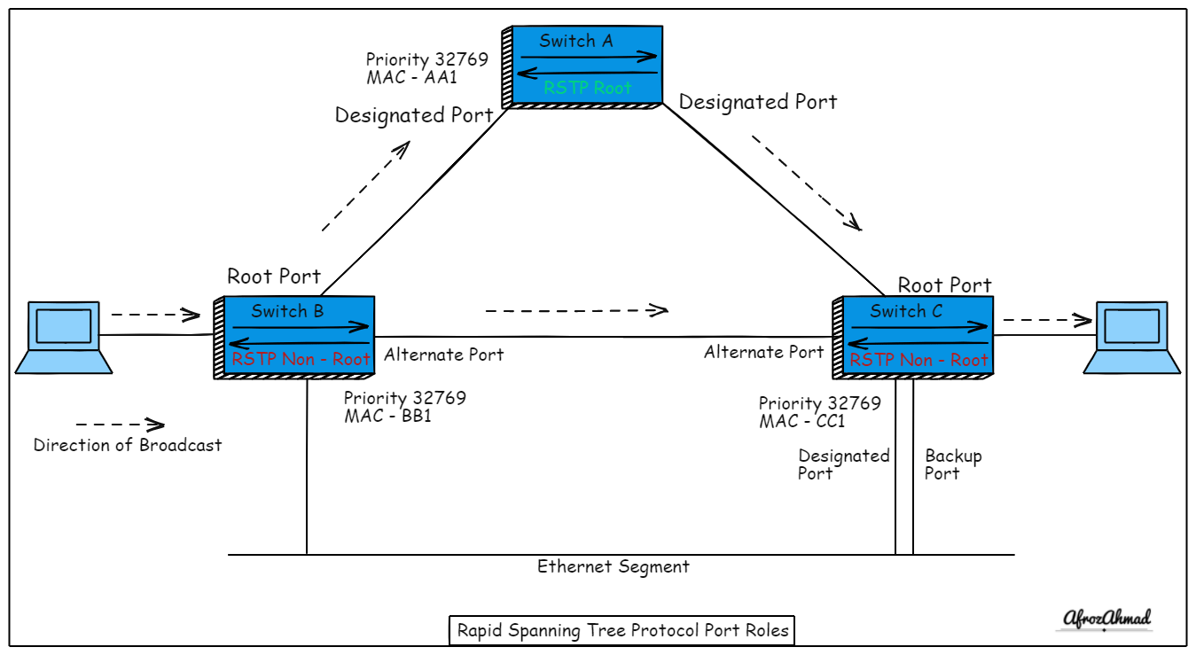
RSTP Port Roles
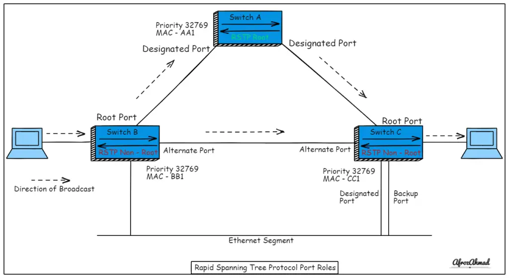
RSTP has four types of port roles.
Root port
It is similar to Spanning Tree (802.1D) and is the port on a switch that is the closest way (Lowest Cost) to the Root Bridge.
Designated port
It is also the same as Spanning Tree (802.1D) and is the port that can send the best BPDU on its segment. All ports on the root switch are designated ports facing downwards away from the root switch.
Alternate Port
An alternate port is a discarding port in a blocked state with an alternate (inferior) path to the root bridge if the root port fails. It is the backup of Root Port.
For example, let’s say a switch has two paths to the root bridge. It will select one of the two ports as a root port, and the other will become an alternate port. If the root port fails, this redundant path (the alternate port) will become the new root port.
Backup Port
Because it has an inferior port path cost, it is a discarding port on the same ethernet segment as the designated port. Therefore, it is the backup of the Designated Port.
In other words, a Backup port in Rapid Spanning Tree Protocol is a port that is not the designated port but is still functioning. If the designated port fails, the backup port will become the designated port.
RSTP Port States
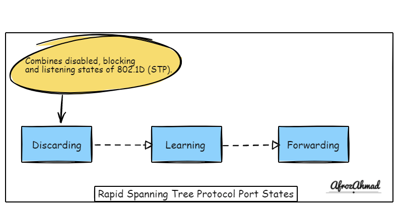
RSTP has only three port states discarding, learning, and forwarding.
What is RSTP Discarding Port State?
The discarding state is when a device is connected, and the port will first enter the state. No MAC addresses are learned for incoming data frames; they are dropped. It combines the disabled, blocking, and listening states of 802.1D (STP).
What is RSTP Learning Port State?
In this state, incoming data frames will be dropped, but MAC addresses are learned.
What is RSTP Forwarding Port State?
The forwarding state is when the port is actively forwarding traffic. Incoming data frames are transmitted according to learned MAC addresses.
Mapping of port states between STP and RSTP:-
| STP State (802.1d) | RSTP State (802.1w) |
| Disabled | Discarding |
| Blocking | Discarding |
| Listening | Discarding |
| Learning | Learning |
| Forwarding | Forwarding |
What is RSTP Port Types?
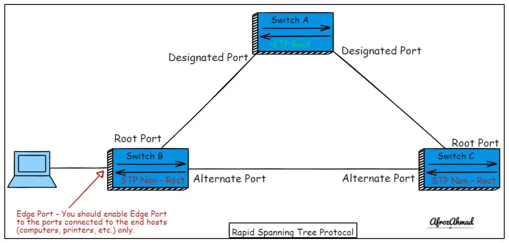
What is the definition of an Edge port?
Edge port includes the functionality of the Cisco Portfast extension. These ports connect exclusively to hosts or end stations similar to Cisco Portfast for Spanning Tree. In addition, edge ports immediately enter the forwarding state, skipping the forwarding delay time.
If an edge port receives a BPDU, the port is treated as a standard spanning-tree port.
What is a Point-to-Point Port?
Ports operating in full-duplex mode are considered point-to-point ports. It skips the forwarding delay and immediately transitions to the forwarding state.
It is configurable via the “spanning-tree link-type.”
What is a Shared Port?
A half-duplex port is a shared port. It is a port that connects to a shared network via a series of bridges. It utilizes the conventional STP mechanism for listening and learning.
How does RSTP work?
In comparison to STP, RSTP works faster by adding an alternate and a backup port into the original Spanning Tree concept. These ports enter the forwarding state immediately rather than waiting passively for the forward delay timer to expire.
Similar to Spanning Tree, BPDUs carry all the RSTP information between the switches. First, let us look into the BPDUs for RSTP.
BPDUs in RSTP
RSTP uses type 2 BPDUs similar to Spanning Tree, making it easy to detect legacy STP switches in the network.
RSTP generates BPDUs at every hello interval (default 2 seconds) and uses them as keepalives between bridges. The most recent BPDU received on a port is saved for up to the max-age timer.
RSTP BPDU ages faster. The max-age timer expires when three consecutive hellos (2×3=6 seconds) from a neighbor are missed. As a result, the previously stored BPDU from that bridge is immediately aged out.
With RSTP, stored BPDUs are generated by neighboring bridges rather than the root bridge, which means they are not validated.
An Inferior BPDU contains worse root bridge information than the BPDU currently stored for the port it was received on.
On the other hand, a superior BPDU contains better information about the root bridge than the BPDU currently stored for the port. And that is the reason, a superior BPDU received on a port overwrites the previous BPDU and promotes it to the root/designated port.
How does RSTP rapidly transitions to a forwarding state?
The Rapid state transition is one of the benefits of RSTP, as it eliminates the need for ports to wait for forwarding delay timers. Only edge and point-to-point ports qualify for rapid transition.
Let us deep dive and check how exactly rapid transitioning works:
When a port becomes online, it is immediately placed in the designated block state. The switch is in this state will wait for BPDUs to arrive. A new root port is discovered when a superior BDPU is learned on the current non-root port (using the Proposal flag).
This initiates the Sync operation. The local port is then designated as the new root port, while the upstream port is in a designated blocking state. Non-edge designated ports are placed in a blocking state during the Sync operation.
After blocking all non-edge designated ports, the local switch immediately authorizes the upstream bridge to transition its port to the designated forwarding state. This is accomplished by setting the Agreement bit in the BPDU that is being transmitted.
The local bridge generates new BPDUs, assigns them the Proposal flag, and sends them out through the blocked ports designated by the local bridge.
The procedure described above is repeated if the receiving downstream switches decide the new BPDU superior. Otherwise, the port between the bridges will be blocked entirely on one end. Edge Ports will remain in the forwarding state.
Why and How RSTP accepts Inferior BPDUs?
To accelerate convergence, RSTP incorporates portions of the Cisco backbone fast concept.
Compared to 802.1D, an inferior BPDU received on a blocked port is accepted and recorded.
Because the bridge that received this is aware that the root bridge is still active, it responds with information about the root bridge via a BPDU.
The inferior BPDU-sending bridge will accept the superior BPDU-receiving bridge and change its root port.
What is RSTP Uplink Fast?
RSTP Uplink Fast is an 802.1w Rapid Spanning Tree Protocol (RSTP) enhancement that allows a switch to transition a port into the forwarding state quickly. It is similar to the Cisco Uplinkfast extension. When a bridge’s root port becomes unavailable, the best alternate port is immediately placed in a forwarding state. The selection of a new root port changes the topology, which clears the CAM table entries associated with it. This allows the switch to resume traffic forwarding on the port quickly.
What is RSTP Topology Change (TCs)?
A TC is a set of packets used to indicate to all switches in the network that a topology change has occurred. Only non-edge ports that transition to the forwarding state generate a TC when using RSTP. RSTP no longer uses the specific TCN BPDU unless notification to a legacy bridge is required.
When a bridge detects a TC, it increments the TC-While timer by two times the hello timer. Following the transmission of the TC, the bridge will flush all MAC addresses. However, the associated MAC addresses are not flushed when a TC message is received at an edge port.
BPDUs are sent out from both the non-edge designated port and the root port during the TC-While.
The TC bit will be set on these BPDUs to indicate that a TC has occurred. Bridges that receive TC bit set, BPDUs flush their entire MAC address table and initiate a TC-While timer.
This results in flooding until all MAC addresses are redetected and re-learned. This mechanism is significantly faster than the 802.1D propagation.
RSTP Configuration and Show Commands on Cisco Switches
| Command | Description |
| switch(config)#spanning-tree mode rapid-pvst | This command enables RPVSTP+ (Cisco version of RSTP) in cisco Switches. You should configure in global configuration mode. |
| switch#show spanning-tree | This command shows RSTP configuration details on a switch. |
| switch#show spanning-tree interface | This command shows information about the spanning-tree state. |
| switch#show spanning-tree summary | This command shows the STP mode enabled. |
| switch(config)# interface fa0/1 | Use this command under Interface configuration mode. |
| duplex full | Hardcode the duplex setting |
| spanning-tree link-type (point-to-point | shared) | Specifies the link type for RSTP fast transition or not (this overwrites the duplex setting) |
What are some of the Best Practices of Rapid Spanning Tree Protocol?
There are a few best practices for RSTP that are important to follow for the network to function correctly.
First, all switches in the network need to be running RSTP to take advantage of its features.
Second, you should use RSTP in smaller topologies; the optimal topology for RSTP is one with few redundant paths, preferably triangle or ring topologies.
Third, You should carefully plan the STP topology to take advantage of RSTP’s fast convergence. And you should always be aware that speed is not always good and required, especially when it comes to the stability of the network. So, check your network SLA before opting for RSTP. I recommend testing RSTP in LAB first before implementing it into the production networks.
Finally, You should know the difference between the Cisco version and the IEEE version of RSTP. Cisco’s version, which is PVRSTP+, is a per VLAN version of RSTP, and the IEEE RSTP version has one instance of RSTP for all VLANs.
Conclusion
In conclusion, RSTP is an evolution of the Spanning Tree Protocol(STP), designed to provide better convergence. RSTP provides faster and more efficient topology changes than the original Spanning Tree Protocol (802.1D). This article explained what is RSTP in networking, its properties, use-cases, and implementation on Cisco switches.
Please share this article and let me know if you have any questions.
- pfSense 10G Home Lab Setup: Complete Hardware Guide (2026) - April 1, 2026
- Best Budget Home Lab Setup Under $300 (2026): Complete Starter Stack - March 30, 2026
- Best Modems for Spectrum: Top DOCSIS 3.1 Picks That Actually Work - March 28, 2026