A Spanning Tree Protocol or STP is a layer2 protocol used to prevent loops in a network by ensuring that a single path exists between any two nodes in the network. In this blog post, I will explain the Spanning Tree protocol, what problems it solves, it’s core components, how it works, and how to configure it, along with best practices.
One more thing before we begin, I will use Spanning Tree Protocol, Spanning Tree, Spanning Tree, or STP interchangeably in this post; all have the same intent. Also, bridge and switch meanings are the same in this post.
I would also like to recommend you to read about VLANs, VLAN tagged vs untagged, and VLAN Trunking Protocol topics to grasp the basic understanding of networking.
What is Spanning Tree Protocol in networking?
The Spanning Tree Protocol, short for STP, is a layer2 network protocol that runs on switches and creates a loop-free topology by blocking the redundant links in the Ethernet networks.
What is the purpose of the spanning tree protocol STP?
The spanning tree algorithm’s main job is to stop layer2 loops and resulting broadcast storms in the logical layer2 topology.
Because STP always creates a single path between two nodes, another purpose of spanning trees is to design a network with redundancy inbuilt through backup links if an active link goes down.
History of Spanning Tree Protocol
Dr. Radia Perlman of Sun Microsystems first invented STP and was specified as IEEE 802.1D.
Then the IEEE defined Rapid Spanning Tree Protocol (RSTP) as 802.1w in 2001. RSTP introduces new convergence behaviors and the bridge port roles for faster network change and failure recovery. In addition, RSTP is backward compatible with STP.
STP was initially specified as IEEE 802.1D, but the capability of spanning tree (802.1D), rapid spanning tree (802.1w), and multiple Spanning tree (802.1s) has since been integrated into IEEE 802.1Q-2014. MSTP is also backward compatible with STP.
Spanning tree protocol types – Spanning tree protocol examples
There are IEEE versions of STP and Cisco proprietary versions of STP.
IEEE Versions of STP includes:-
- IEEE 802.1D, which is the original STP version. One STP instance for all VLANs.
- IEEE 802.1w, which is Rapid STP or RSTP. It has faster convergence than STP.
- IEEE 802.1s, which is Multiple Spanning Tree Protocol or MSTP. IEEE response to Cisco’s Per VLAN STP, you can map various VLAN into a single STP instance.
Cisco Proprietary Versions of STP includes:-
- Per VLAN STP+ or PVSTP, it has 1 STP instance per VLAN.
- Per VLAN Rapid STP or R-PVSTP+ or PVRSTP, it is faster than PVSTP.
Spanning tree protocol explained – How Spanning tree protocol works?
STP elects a root bridge in the network. The root bridge is the center of the spanning tree, and all other bridges must travel via the shortest path possible to reach the root bridge. The spanning-tree calculates the cost of each path from each bridge in the network to the root bridge. Only the path with the lowest cost is kept and used. Rest all the other paths are put on hold by placing those ports into a blocking state.
The above functions and many more are performed by exchanging BPDUs (Bridge Protocol Data Unit) between the switches every 2 seconds.
Let us understand BPDU first.
What is BPDU (Bridge Protocol Data Unit)?
BPDU (Bridge Protocol Data Unit) carries essential messages for STP. Below are the details.
- BPDUs are 8 byte control frames that carry STP information between switches.
- STP employs BPDUs to select a single root bridge and discover/promote TCs (Topology Changes).
- BPDUs include the data necessary to assign distinct port responsibilities between switches and detect/avoid loops.
- Only the root bridge sends BPDUs in a stable STP (802.1D) topology, while other bridges relay the root bridge BPDUs.
- The most recent BPDU received on each port is saved for up to the timer’s maximum age.
- An inferior BPDU contains root bridge information that is worse than the BPDU currently stored for the port on which it was received.
- A superior BPDU contains root bridge information that is superior to the BPDU currently stored for the port it was received on.
- When a superior BPDU is received on a port, the previous BPDU is overwritten, and the port is promoted to root/designated port.
- BPDUs are generated per-VLAN with PvST.
- PvST BPDUs include the VLAN-ID in a ‘PVID’ TLV field, the sending port’s MAC address, and a destination multicast MAC of 0100.0ccc.cccd.
Let us now look at all the operations performed by STP inside switches:-
What is a Root Bridge?
The root bridge is the authoritative starting point for computing the loop-free spanning-tree structure. As a result, all bridges should only have one active link, known as the root port, to that particular root bridge.
A VLAN’s root bridge ports will be in the designated forwarding state. The root bridge broadcasts BPDUs with a root path cost of 0.
What is the process of election of a root bridge?
The first step of the STP process is to elect the root bridge in the network.
The bridge with the lowest Bridge ID is chosen as the STP root bridge.
When a switch boots, it assumes it is the root bridge and sets the Root ID in all outgoing BPDUs to the local Bridge ID. If it receives a BPDU with a lower root ID, it considers that switch as a root switch. The local switch then starts sending BPDUs with that root ID.
On a root bridge, the output of “show spanning-tree” will show:
>> ‘this bridge is root.’
>> The same Priority and MAC address for both the Root ID and Bridge ID.
Now let us understand Bridge ID and Root ID.

A bridge ID is assigned to each switch. The bridge ID is 8 bytes and it is formed by combining the bridge priority (2 Bytes) and the MAC address (6 bytes) of the switch.
The bridge priority is a two-byte field that can be configured with a default value of 32,768 and configured in increments of 4096.
The lower the bridge ID value, the more likely the bridge becomes the root bridge. The bridge with the lowest bridge ID becomes the root bridge always.
Like Bridge ID, a Root ID consists of a root priority and a MAC address. By default, the root priority is set to 32768 (0×8000) and can be configured in increments of 4096. The lower root MAC address is used to break a tie if the root priorities of the two switches are equal.
What is the root port, and how is it selected to determine the best path to the root bridge?
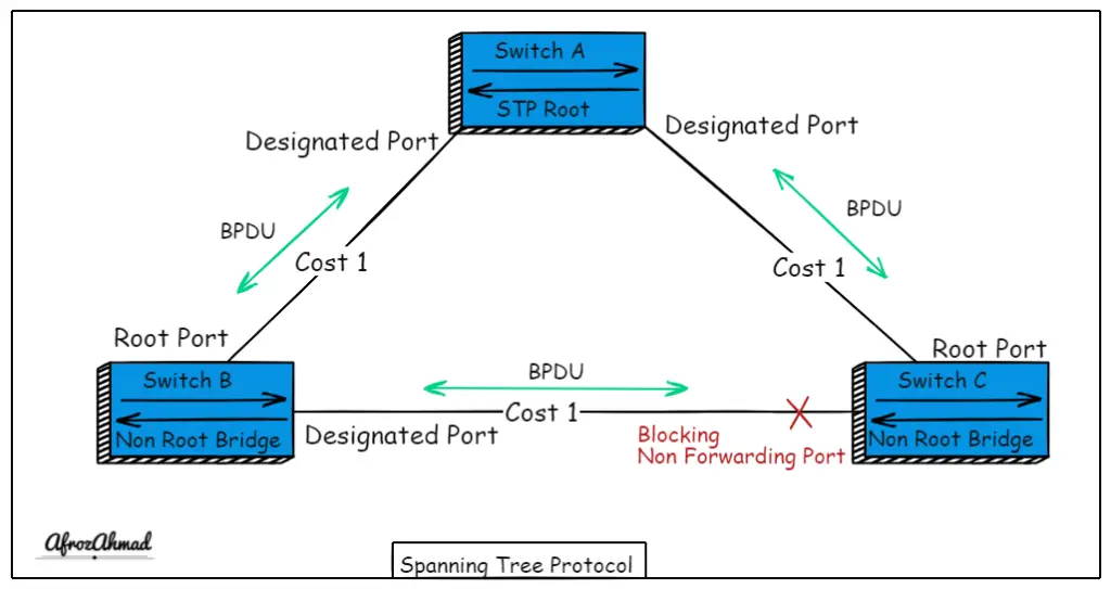
That port with the lowest/shortest distance to the root bridge is the root port on a switch that is not a root bridge or (NRB – Non-Root Bridge).
Root bridges only have Designated ports rather than root ports.
After the election of the root bridge in the network, the next step is to calculate the best path from each switch to the root bridge.
The local switch checks the BPDUs received on ports. If BPDU packets from the root bridge are received on multiple ports, then multiple paths to the root bridge exist in the network.
The best path is then considered to be through the port that received the BPDU with the lowest path cost. As BPDUs are forwarded from one bridge to another bridge, path costs are calculated by adding each bridge’s port priority to the initial path cost.
– How a Root Port is selected?
- 1st- Lowest cumulative cost to the root bridge:
- It is the sum of all the port cost values towards the root bridge.
- The default values are inversely based on interface bandwidth, i.e., a higher bandwidth interface will have a lower cost.
- The port cost can be changed manually using “spanning-tree cost.”
- 2nd- Lowest upstream BID:
- They are used to choose one bridge over another when two uplinks to different bridges are available.
- Third- Lowest port ID:
- The lowest port priority (0-255), default, is 128.
- The lowest port number value assigned by IOS software, e.g., Fa0/1, may have a port number of 1.
What is a Designated port, and how to choose the designated port on each segment?
Designated ports are the ports facing downstream away from the root bridge. And that is the reason the root bridge has designated ports only.
A designated port is in charge of sending and receiving traffic on a segment shared by two or more non-root bridges.
The steps to choosing a Designated port are similar to choosing a root port mentioned above in the root port section.
Quick Tip: Only the Root and Designated ports learn MAC addresses on switches.
Election of a designated bridge on each segment
A designated bridge is a switch/bridge on a given segment with the designated port. That’s why the root bridge becomes the designated bridge for all directly connected segments.
If two switches on a segment have root ports, the bridge with the lowest bridge ID becomes the designated bridge.
Blocking non-forwarding ports
If a port is not a root or designated port and has received BPDUs, those ports are put into a blocking state. Although they are administratively up, these ports are not permitted to forward traffic (they still can generate and receive BPDUs). This type of port is also referred to as an alternate port or backup port in RSTP.
How to Influence Root or Designated port Election?
You can use the below commands to change the cost and Priority of the local switch, which in turn will influence the Root and Designated port election process of STP.
Port Cost
- It can be changed to influence how the local bridge chooses its root/designated port.
- Cost can be changed under switch port interface by
- Interface F0/5
- spanning-tree [vlan] cost {value}
- Changing the port cost will affect all downstream switches because root path cost is the sum of all port costs to the root.
Port Priority
- It can be changed to influence how a downstream bridge selects its root/designated port.
- You can change Priority by the below interface mode command.
- Interface Fa0/1
- spanning-tree [vlan] port-priority {value)
- However, port priority is only significant between two directly connected bridges. You can check the port priority of a neighboring bridge by using “show span VLAN id detail” as ‘designated port id x.x’.
Spanning Tree Protocol states
When a port on a switch is brought online, it goes through a series of spanning-tree port states. These states change in a predictable pattern based on the information derived from BPDUs received on the port.
Spanning tree has the following states on a port:
Disabled
A port is in the downstate and not part of STP.
Initializing
A port in the initializing state has recently been powered on or removed from the administratively downstate.
Blocking
A port that is blocking is essentially idle. The blocking delay is 20 seconds.
- The port cannot forward or receive frames or record MAC addresses.
- The port is responsible for receiving and processing BPDUs only.
- The port can receive and respond to network management messages if required.
Listening
The listening state is similar to the blocking state, except that BPDUs are sent and received in this state. Again, frame forwarding remains prohibited, and no addresses are learned.
The listening delay is 15 seconds.
Learning
A port in the learning state does not forward frames, but it does analyze frames that come in and retrieve the MAC addresses from those frames and them into the MAC address table or CAM table. The frames are discarded after they have been analyzed.
The learning delay is 15 seconds.
Forwarding
You can think of the forwarding state as the “normal” state. In this state, a port receives and transmits BPDUs, examines incoming packets for MAC address information, and forwards frames from other switch ports.
When a port is in the forwarding state, the device or network connected to it is active and ready to communicate.
Disabled
A disabled port does not forward frames and is not a member of the spanning tree. It only accepts and responds to network management messages.
Critical information concerning STP port states
- The IEEE standard requires that the values of the Listening and Learning timers be equal.
- The blocking state delay applies only when a port first initializes, i.e., after a reboot, not when a port changes to forwarding.
- When a port initially comes up, the total delay is 50 seconds (20+15+15) with no data transmission.
- When a port enters the forwarding state, the delay is solely the listening and forwarding delay, e.g., when a port is unshutting.
- And when a port changes status, the total delay is merely 30 seconds (15+15) of data flow being unavailable.
What are Spanning Tree Topology Change Notifications?
- STP TC’s (Topology Notification) in 802.1D is caused by:
- A forwarding port changes its state.
- For example, a previously blocked port has been moved to the forwarding state.
- When a bridge detects a Topology Change (TC), it sends a TCN (Topology Change Notification) to the root bridge.
- The root bridge sets the TC flag on the next set of BPDUs it sends out to notify all bridges of the Topology Change.
- The receiving bridges relay these BDPUs to all downstream bridges in the network.
- Bridges that receive a BPDU with the TC bit set reduce their MAC address aging time to the forwarding time.
- During topology changes, cleaning the MAC address table is required, but it causes unicast flooding to learn the flushed MAC addresses again.
- Excessive flooding may hurt the performance and stability of your network.
- When a port fast port is up or down, no TC events are generated.
Additional Spanning Tree Protocol Features
The STP was originally intended for bridges with a limited number of ports. However, the spanning tree was improved with the introduction of Ethernet switches. These enhancements helped make the spanning tree more favorable by shortening the time a host must wait for a port and shortening the time it takes to reach a point of convergence in a Layer-2 network.
What is Portfast?
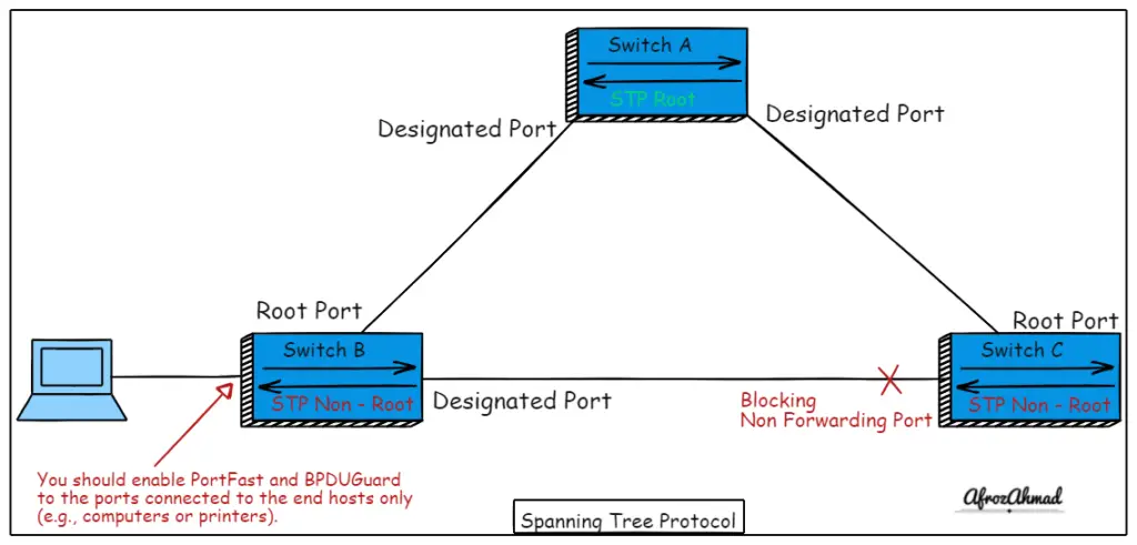
PortFast is a Cisco switch feature that allows a port to skip all other spanning tree states and proceed directly to the forwarding state.
PortFast should be enabled only on ports that are not connected to switches.
A standard port takes about 30 seconds to enter the forwarding state in a spanning tree, which can cause systems using DHCP to time out and not receive an IP address. Enabling the PortFast feature on a port solves this problem.
- Use the “spanning-tree portfast” interface command to enable PortFast on an IOS switch.
- When you enable PortFast, the switch will issue the following warning about the dangers of the feature:
Switch-01(config-if)#spanning-tree portfast
%Warning: portfast should only be enabled on ports connected to a single host. Connecting hubs, concentrators, switches, bridges, etc… to this interface when portfast is enabled, can cause temporary bridging loops.
Use with CAUTION
%Portfast has been configured on FastEthernet0/20 but will only have effect when the interface is in a non-trunking mode.
- You can disable Portfast by the following command.
- Switch-01(config-if)#no spanning-tree portfast
Quick Tip:- You must take extra precautions when using this feature. If a switch is connected to a port that has PortFast enabled, a loop may occur.
What does BPDUGuard do?
As long as ports configured for PortFast are connected to devices other than switches/bridges, they should never receive BPDUs. A bridging loop will occur if a PortFast-enabled port is connected to a switch. Cisco created a feature called BPDU Guard to prevent this.
- When a port configured for PortFast receives a BPDU, BPDU Guard disables it automatically.
- The port is not put into blocking mode; instead, it is set to ErrDisable. If this occurs, you must reset the interface.
- In IOS, the “spanning-tree bpduguard enable” command is used to enable BPDU Guard:
- Switch-01(config-if)#spanning-tree bpduguard enable
- To disable this feature, change the enable keyword to disable.
- Switch-01(config-if)#spanning-tree bpduguard disable
What does UplinkFast do?
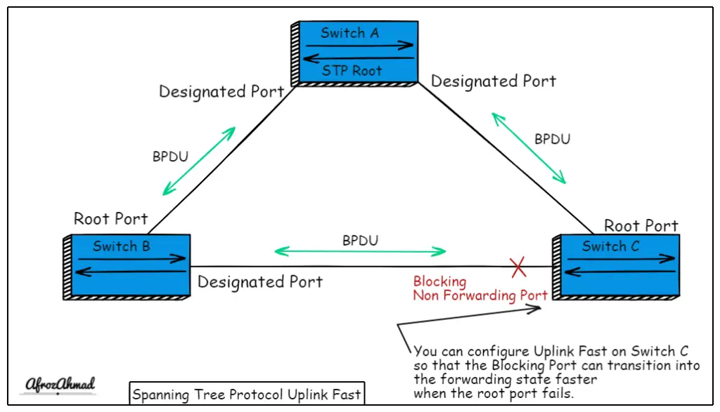
UplinkFast is an access-layer switch-specific feature. These switches typically connect to the distribution layer via links to other switches. When a link on the designated port fails, a port with an alternate path to the root bridge usually is cycled through the spanning-tree listening and learning states until it returns to the forwarding state. Only then will the port be able to handle the traffic. This process can take up to 45 seconds.
- In other words, UplinkFast allows a blocked uplink port to bypass the listening and learning states when the designated port fails.
- This feature impacts all VLANs on the switch and allows the network to recover faster.
- But you should know that enabling UplinkFast modifies priorities in switches.
- It lowers the bridge priority to 49,152 to prevent the switch from becoming the root bridge.
- Configuring UplinkFast in IOS-based switches is easy.
- Switch-01(config)#spanning-tree uplinkfast
- Disabling the feature (via no spanning-tree uplinkfast) resets the priorities to their defaults.
- Again, this may not be what you want or expect, so proceed with caution.
What is spanning tree BackboneFast?
- BackboneFast detects indirect link failures.
- It actively discovers paths to the root by sending root link query PDUs after a link failure.
- When it finds a path, it resets the max-age timer to 0, allowing the port to cycle through the normal listening, learning, and forwarding states without having to wait another 20 seconds.
- BackboneFast can be enabled on the switches in the global mode:-
- Switch-01(config)#spanning-tree backbonefast
- Negating the command disables the feature.
- Switch-01(config)#no spanning-tree backbonefast
Quick Tip:- You should always enable backbone fast on all switches in the network.
What is BPDU Filter?
You can say BPDUFilter is the lighter version of BPDUguard.
- BPDUFilter discards all inbound BDPUs and does not send any BDPUs out of the port.
- Unlike the BPDU guard, the port does not go into an err-disabled mode when a violation occurs.
- Data traffic will continue to be forwarded.
- If the BPDU filter default is enabled with portfast, all ports except those receiving BPDUs will run in portfast mode.
- BPDUFilter can be enabled globally.
- Switch-01(config)#spanning-tree portfast bpdufilter default
- Switch-01(config)# no spanning-tree portfast bpdufilter default -> To disable it.
- You can enable it inside the interface as well.
- Switch-01(config-if)#spanning-tree bpdufilter enable
- Switch-01(config-if)#no spanning-tree bpdufilter enable -> To disable it.
What is Root Guard?
- Like a BDPU guard, a spanning tree root guard port is only disabled if a superior BPDU is received, putting the port in a ‘ROOT INCONSISTENT STATE.’
- You should enable it on downstream ports that will never become a root port.
- A better BPDU indicates a lower root bridge cost than installed.
- You can enable Root Guard inside Interface configuration.
- Switch-01(config-if)#spanning-tree guard root
- Root Guard can be disabled inside the Interface configuration.
- Switch-01(config-if)#no spanning-tree guard root
What is Loop Guard?
- Loop Guard is used to preventing STP loops caused by a unidirectional link.
- Similar to UDLD, but instead determines unidirectional traffic using BDPU keepalive.
- A loop can occur if a blocked port incorrectly transitions to the forwarding state.
- Blocked ports will be transitioned into a ‘LOOP INCONSISTENT STATE’ to avoid loops.
- You can enable Loop Guard inside Interface configuration.
- Switch-01(config-if)#spanning-tree guard loop.
- Loop Guard is disabled inside Interface configuration.
- Switch-01(config-if)#no spanning-tree guard loop.
What is UDLD (Uni-Directional Link Detection)?
UDLD is Cisco proprietary, and it is used to detect unidirectional links, mainly in fibers.
- UDLD Detects a bidirectional link failure and uses UDLD hellos to prevent unidirectional link loops.
- You should enable UDLD on both sides of a link.
- Peers find each other by sending frames to the MAC address 0100:0CCC:CCCC.
- The global command “udld enable” only works on fiber ports.
- Use the interface command “udld port aggressive” to enable UDLD for copper ports.
- There are two modes:
- Normal – This informational mode generates a log entry but does not disable or shut down the port.
- Aggressive – This mode will place a port in the ERR-Disable state.
Spanning tree protocol Cisco configuration
Spanning tree is enabled by default in all cisco switches.
You can see its status by using the below show commands in IOS and NX-OS based cisco switches:
- S
how spanning-tree -> It shows the STP information of each VLAN in detail. Show spanning-tree summary -> This command shows you the status of features like UplinkFast and BackboneFast.Show spanning-tree root -> Shows information of root bridge for every VLAN.Show spanning-tree [vlan {id}] [detail] --> Shows the root bridge, the local Root ID, and Bridge ID also shows root, designated, and alternate port details.
Spanning Tree Global config Commands in IOS based Cisco switches:-
spanning-tree mode {pvst | rapid-pvst | mst} --> Configures the spanning-tree mode (default = PVST)spanning-tree vlan {id/s} priority {value}Manually configure the bridge priority (default = (32768 + sys-id-ext){value}: Must be increments of 4096 (lowest value is preferred)
spanning-tree vlan {id/s} root {primary | secondary} [diameter {2-7}]{primary}: Sets a priority of 24576, if not low enough, 4096 is used{secondary}: Sets a priority of 28672[diameter]: Maximum number of switches between any two points.
no spanning-tree extend system-id --> This command is ised to disable sys-id-ext (default = enabled) (PVST & Rapid PVST only)spanning-tree vlan {id/s} hello-time --> Configures the hello interval (default = 2sec)spanning-tree vlan {id/s} forward-time --> Configures the forward delay (default = 15sec for each delay)spanning-tree vlan {id/s} max-age --> Configures the max age interval (default = 20sec)no spanning-tree vlan {vlan-id} --> Disables STP on a per VLAN basis.
Spanning Tree Troubleshooting Commands in IOS-based Cisco switches:-
debug spanning-tree events --> Used to see port state changesdebug spanning-tree bpdu [transmit|receive] --> Used to debug the BPDUs sent and received.
The rest of the STP config commands are mentioned in their respective sections.
Cisco Spanning tree best practices
Always Configure a Root Bridge
- In production networks, the positioning of the root bridge is critical for optimizing traffic flows.
- Don’t let the spanning-tree choose the root bridge on its own.
- Choose which switch in your network will be the root, and give it a bridge priority of 1.
- If you let the switches choose, they may not only choose one that makes no sense.
- Switches added later may also assume the role of the root bridge.
- As the network discovers paths to the new root bridge, the entire network will reconverge, and links will change states.
If possible, use routing instead of switching.
“Switch when you can, route when you have to,” used to be the old network expression. This mantra, however, no longer holds in today’s world of fast Layer-3 switching.
Layer-3 switches allow you to route at switching speeds. Layer-3 redundancy is easy to understand than Layer-2 redundancy. Using routing to solve your redundancy concerns is acceptable if the business needs are met, and the result is the same.
Other best practices are looking and avoiding loop contributors mentioned below when designing or troubleshooting the Spanning tree.
The majority of STP loops arise due to high BPDU loss, which causes blocked ports to convert to forwarding mode.
Other possible loop contributors include the following:
- Duplex mismatches.
- Unidirectional link problems.
- Switch resource problems.
- Incorrect port fast configuration.
- Incorrect BPDU filter configuration.
- Incorrect flex link configuration.
- Incorrect disabling of STP.
- Physically connected loop.
- Software errors.
- STP mode mismatch between switches in the same network.
Conclusion
STP is a protocol that allows switches to prevent network loops. STP is enabled by default in Cisco switches and must be used to stop network loops. This article has explained the Spanning Tree Protocol (STP) concept, how it works, its port states, and additional STP features. Then, we discussed how to configure and check STP in your network and ended the article with the best practices. Let me know if you want me to add anything else to this article. Please share this article so that it reaches the maximum number of people.
Frequently Asked Questions – FAQs
How to disable STP?
STP cannot be disabled on a per-port basis, but it can be disabled per-VLAN or globally on the switch.
The command “no spanning-tree VLAN vlan-id” can be used to disable STP on a per VLAN basis.
Alternatively, the BPDUs on a port could be filtered by the BPDUFilter command to simulate ‘disabling’ STP on the port.
FLEX-links can also disable STP on a port, but use it with caution.
- pfSense 10G Home Lab Setup: Complete Hardware Guide (2026) - April 1, 2026
- Best Budget Home Lab Setup Under $300 (2026): Complete Starter Stack - March 30, 2026
- Best Modems for Spectrum: Top DOCSIS 3.1 Picks That Actually Work - March 28, 2026